CHAPTER 7 CALIBRATION
E5EK
7--4
7.2 Calibrating Thermocouple
• Calibrate according to the type of thermocouple, thermocouple 1
group(K1,J1,L1,E,N,W,PLII)andthermocouple2group(K2,J2,
L2,R,S,B,T,U).
• When calibrating, do not cover the bottom or top of the controller.
Also, do not touch the input terminals (Nos. 11 and 12) and compen-
sating conductor on the E5EK controller.
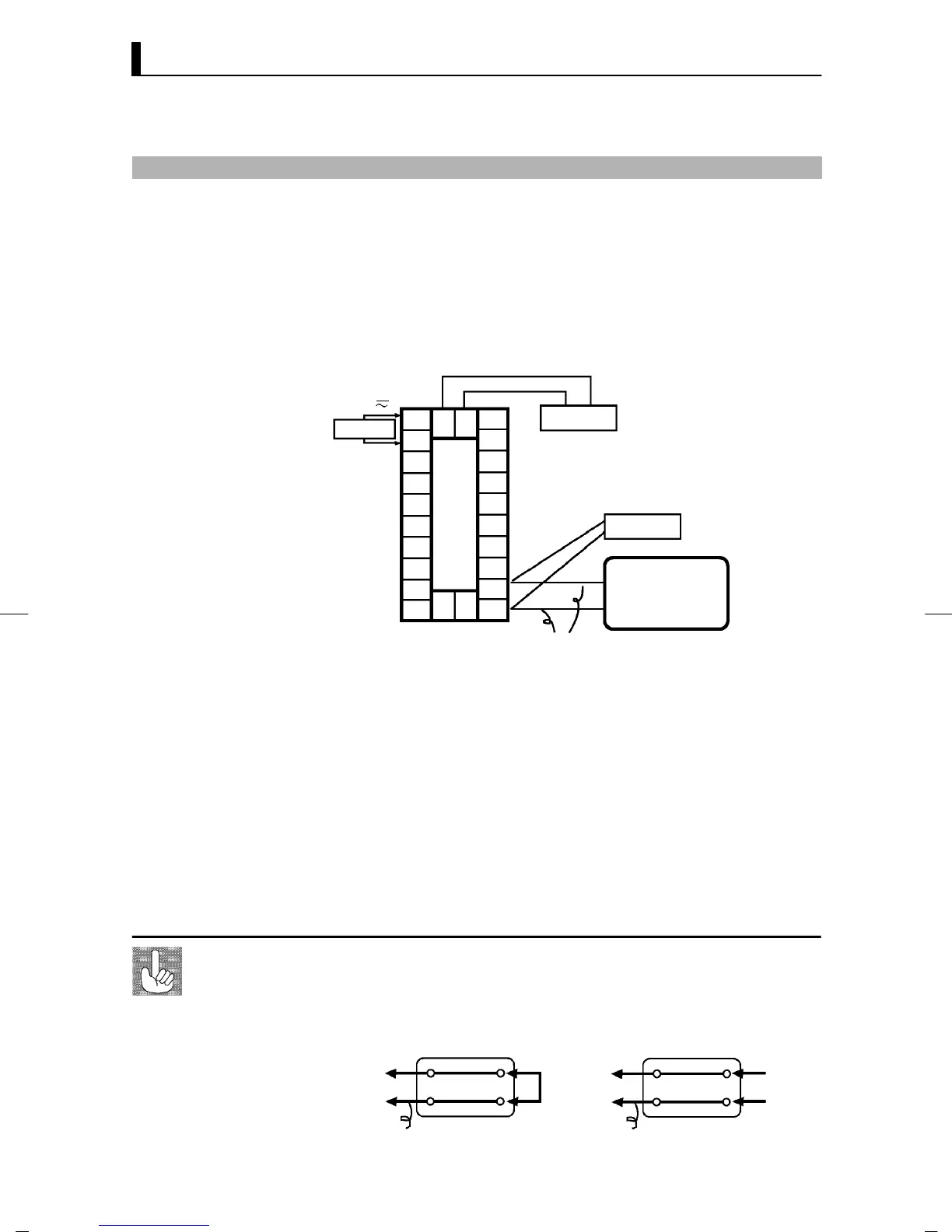
F Preparations
10
9
8
7
6
5
4
3
2
1
20
19
18
17
16
15
14
13
12
11
21 22
23
DMM
STV
Cold junction
compensator
0_C/32_F
Compensating
conductor
SOURCE
AC100-240V
(AC/DC24V )
~
• Set the cold junction compensator to 0_C. However , make sure that
internal thermocouples are disabled (tips are open).
• In the above figure, STV refers to a standard DC current/voltage
source, and DMM refers to a precision digital multimeter.
However, note that DMM is required only when the transfer output
function is supported.
• Use the compensating conductor selected thermocouple. However,
note that when thermocouple R, S, E, B, W or PL II is used, the cold
junction compensator and the compensating conductor can be substi -
tuted with the cold junction compensator and the compensating con-
ductor for thermocouple K.
Correct process values cannot be obtained if you touch the contact ends of the
compensating conductor during calibration of a thermocouple. Accordingly, short
(enable) or open (disable) the tip of the compensating conductor inside the cold
junction compensator as shown in the figure below to create a contact or non-
contact state for the cold junction compensator.
Connecting the
Cold Junction Con-
ductor
0°C/32°F0°C/32°F
Cold junction
compensator
Cold junction
compensator
E5EK
controller
E5EK
controller
Compensating conductor Compensating conductor
Short
Open