5-12
The
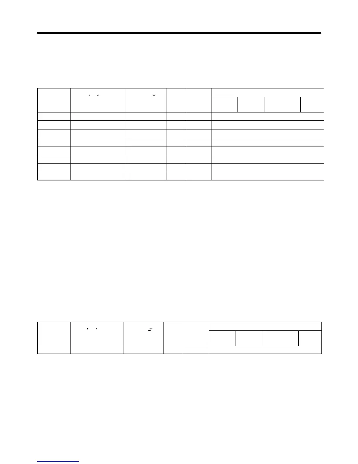
acceleration time is
the time required to go from 0% to 100% of the maximum frequency and the
deceleration time is the time required to go from 100% to 0% of the maximum frequency.
Four
acceleration times and four deceleration times can be set. When using acceleration/deceleration
times 2 through 4, set “Multi-Accel/Decel 1” or “Multi-Accel/Decel 2” in the multi-function inputs (H1-01
through H1-06).
Parameter Display name Setting
range (See
note 1.)
setting
V/f
Control
V/f with
PG
Open Loop
Vector
Flux
Vector
C1-01 Acceleration time 1 0.0 to 6000.0 s 10.0 Quick-start, Basic, or Advanced
C1-02 Deceleration time 1 0.0 to 6000.0 s 10.0 Quick-start, Basic, or Advanced
C1-03 Acceleration time 2 0.0 to 6000.0 s 10.0 Basic or Advanced
C1-04 Deceleration time 2 0.0 to 6000.0 s 10.0 Basic or Advanced
C1-05 Acceleration time 3 0.0 to 6000.0 s 10.0 Advanced
C1-06 Deceleration time 3 0.0 to 6000.0 s 10.0 Advanced
C1-07 Acceleration time 4 0.0 to 6000.0 s 10.0 Advanced
C1-08 Deceleration time 4 0.0 to 6000.0 s 10.0 Advanced
Note 1. The
setting range for the acceleration/deceleration times depends upon the
setting in C1-10
(Acc/Dec
Units). The table shows the setting range when the factory setting is used for C1-10.
If C1-10 is set to “0,” the setting range will be 0.00 to 600.00 s.
Note 2. Parameters C1-01 through C1-04 can be changed during operation, but C1-05 through
C1-08 cannot.
H Emergency Stop Time Setting (C1-09)
Parameter
C1-09 sets the deceleration time that will be used when an emergency
stop signal is input or
a
fault is detected; it can be changed during operation. The deceleration time is the time required to go
from 100% to 0% of the maximum frequency.
When
using an emergency stop input, set a multi-function input (H1-01 through H1-06) to “Fast-Stop.”
The emergency stop time is effective for the following faults. Set a stopping method for each.
• Inverter overheating (OH) pre-alarm: Set in L8-03.
• Pulse generator faults: Set in F1-02 through F1-04.
Parameter Display name Setting
range (See
note.)
setting
V/f
Control
V/f with
PG
Open Loop
Vector
Flux
Vector
C1-09 Fast Stop Time 0.0 to 6000.0 s 10.0 Basic or Advanced
Note The
setting range for the emergency stop deceleration time depends upon the setting in C1-10
(Acc/Dec
Units). The table shows the setting range when the factory setting is used for C1-10. If
C1-10 is set to “0,” the setting range will be 0.00 to 600.00 s.
H Acceleration/Deceleration Time Switching Frequency (C1-11)
When
the acceleration/deceleration time switching
frequency is set in C1-1
1, the acceleration and de
-
celeration
times will be changed automatically as the frequency passes the set level. This parameter
cannot be changed during operation.
Basic Operation Chapter
5