EasyManuals Logo

Omron SYSDRIVE 3G3FV User Manual

Omron SYSDRIVE 3G3FV
400 pages
To Next Page IconTo Next Page
To Previous Page IconTo Previous Page
Page #50 background imageLoading...
Page #50 background image
2-18
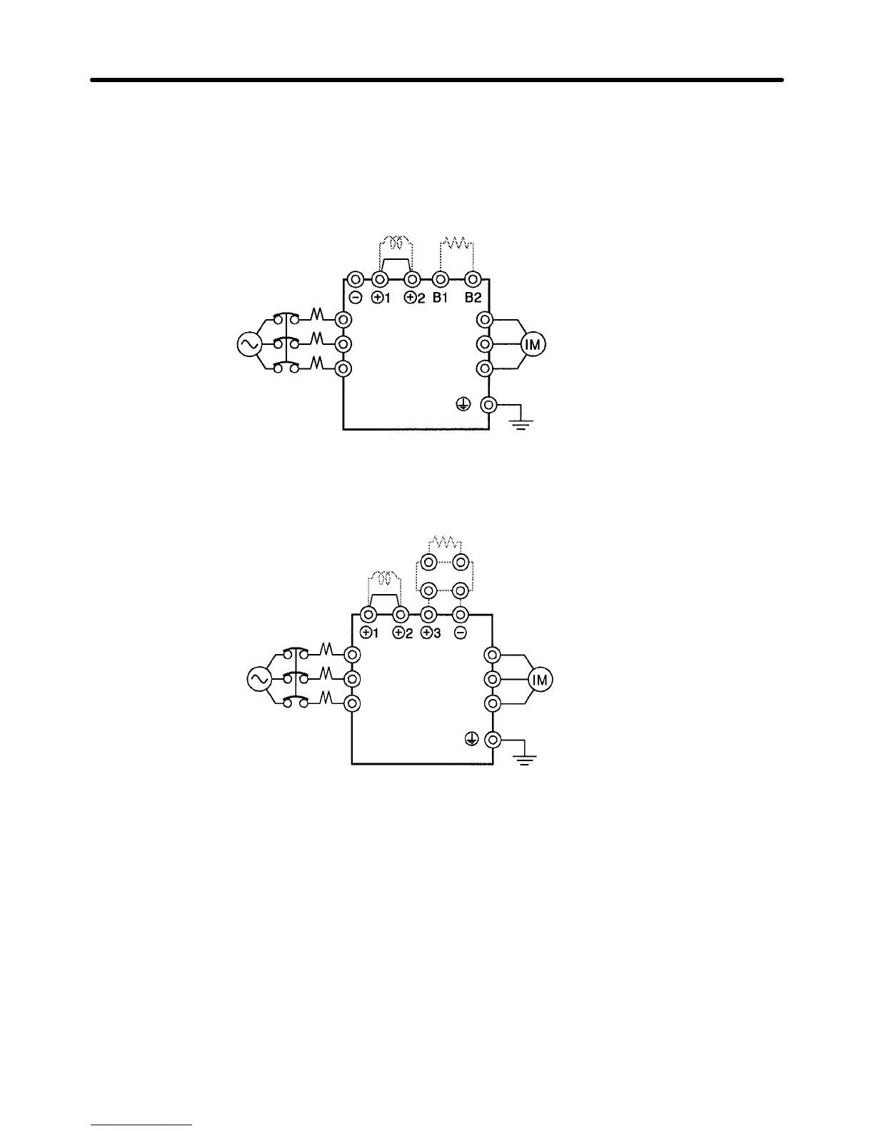
2-2-3 Standard Connection Diagram
H Main Circuit Terminal Connections
D 3G3FV-A2004 to A2075, A4004 to A4150
Note: Be sure to remove the short bar before connecting a DC reactor.
DC reactor (optional) Braking Resistor Unit (optional)
3-phase 200 VAC
(400 VAC)
L1 (R)
L2 (S)
L3 (T)
T1 (U)
T2 (V)
T3 (W)
D 3G3FV-A2110 to A2150
DC reactor (optional)
Braking Resistor Unit (optional)
3-phase VAC
(200 VAC)
Braking Unit (optional)
Note: Be sure to remove the short bar before connecting a DC reactor.
L1 (R)
L2 (S)
L3 (T)
T1 (U)
T2 (V)
T3 (W)
Installation Chapter
2

Table of Contents

Questions and Answers:

Question and Answer IconNeed help?

Do you have a question about the Omron SYSDRIVE 3G3FV and is the answer not in the manual?

Omron SYSDRIVE 3G3FV Specifications

General IconGeneral
BrandOmron
ModelSYSDRIVE 3G3FV
CategoryInverter
LanguageEnglish

Related product manuals