5-41
H Adjusting Speed Loop (ASR) Responsiveness (C5-06) and Integral
Limit (C5-08)
Normally
it isn’t necessary to make this adjustment, but parameter C5-06 can be used when adjusting
the
gain doesn’t remove motor vibration, or adjusting the gain removes vibration but results in poor re
-
sponsiveness. A high C5-06 setting lowers the responsiveness
of
the speed control loop, but makes it
difficult for vibration to develop. This parameter cannot be changed during operation.
Parameter Display name Setting range Units Default
Valid access levels*
number
setting
V/f
Control
V/f with
PG
Open Loop
Vector
Flux
Vector
C5-08 ASR 1 Limit 0 to 400 --- 400 X X X A
The
setting of C5-08 does not normally need to be changed. It is used to set an upper limit for the integral
used
in speed control. Set a smaller value if rapid changes in the load can damage the load or cause the
motor to become disengaged due to Inverter
responsiveness.
If the setting is too small, however
, it may
become impossible to perform speed control.
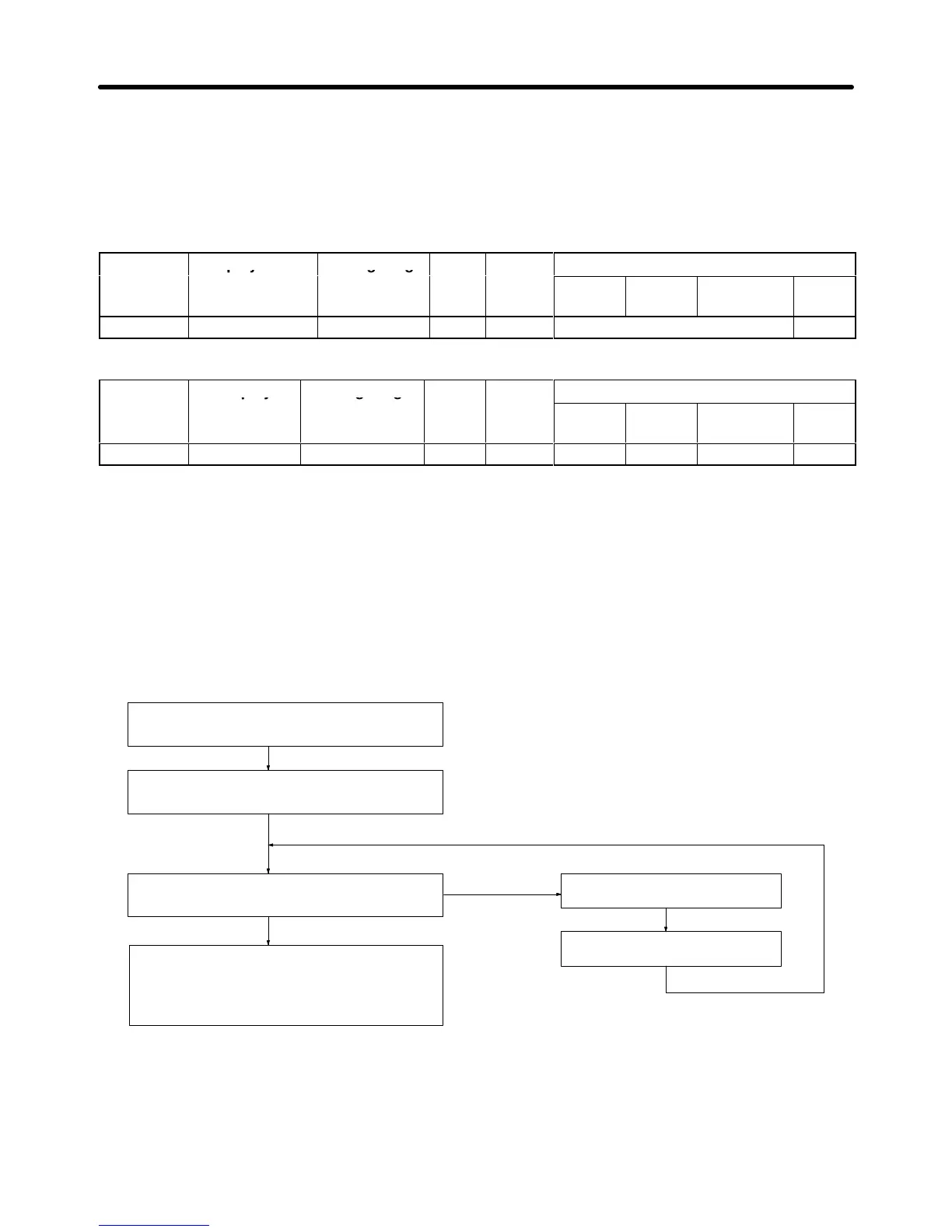
5-4-5 Adjusting Speed Control Loop (ASR) Gain
H Gain Adjustment Procedure
Use
the following procedure to adjust the gain with the mechanical
system and actual load connected.
At zero-speed, increase C5-01 (ASR P Gain 1)
until there is no vibration.
At zero-speed, decrease C5-02 (ASR I Time 1)
until there is no vibration.
Does vibration develop when the motor operates
at the maximum normal operating speed?
Adjustment completed.
(When there is higher-level position control, ad-
just the position loop gain so that overshooting/
undershooting doesn’t occur.)
NO
YES
Decrease C5-01 (ASR P Gain 1).
Increase C5-02 (ASR I Time 1).
H Fine Adjustments
When
you want even finer gain adjustment, adjust the gain while observing the speed waveform. Pa
-
rameter
settings like those shown in the following table will be necessary to observe the speed wave
-
form.
Basic Operation Chapter
5