6-5
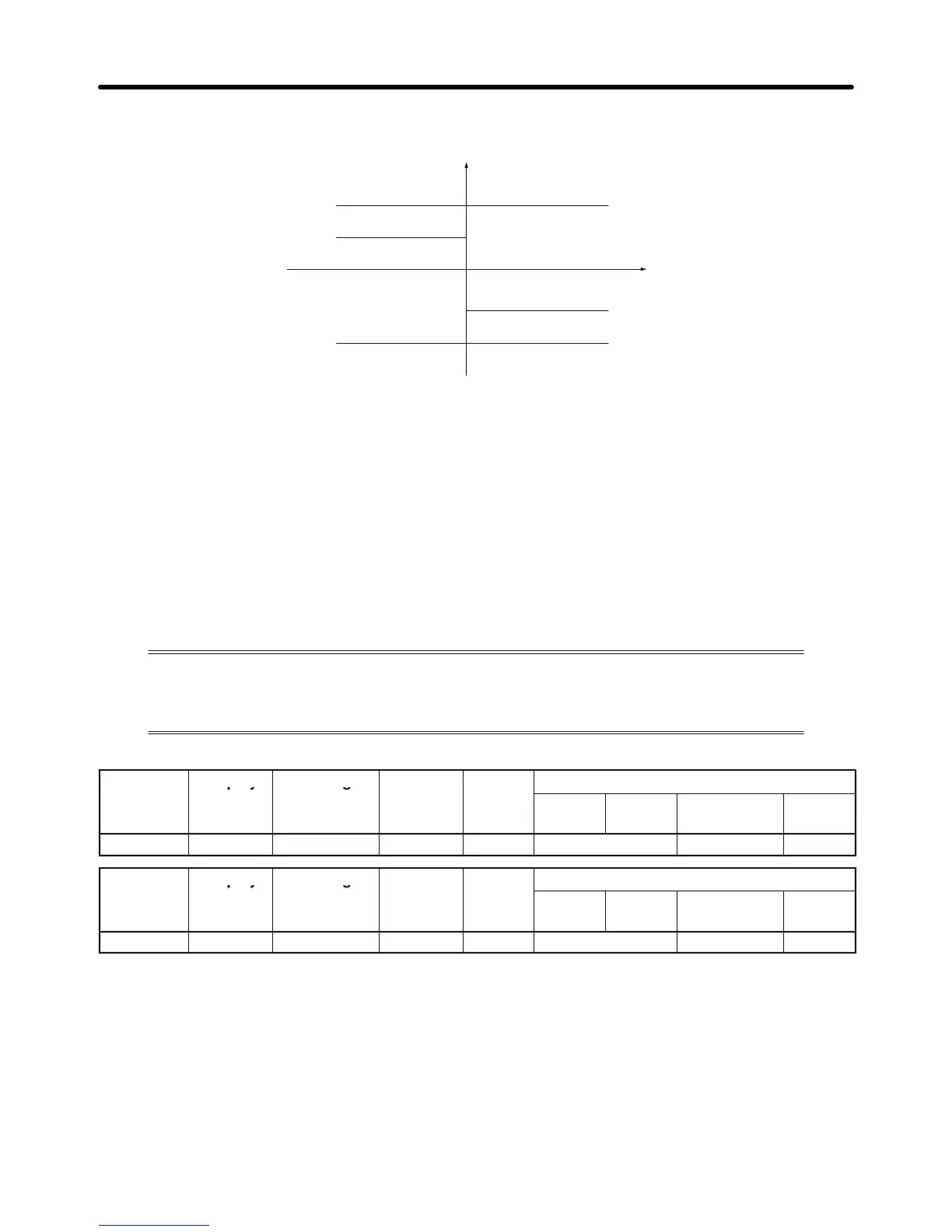
The following diagram shows the relationship between the output torque and each torque limit.
Output torque
Forward direction
Reverse direction
ForwardReverse
Forward torque limit
Regenerative torque limit
Reverse torque limit
Regenerative torque limit
Note 1. When
the forward torque limit has been set, the analog input signal acts as the limit value for
torque generated in the forward direction. The torque limit input is effective when torque is
generated in the forward direction even if the motor is operating in reverse (regenerative
torque).
Note 2. The
torque limit is 100% of the motor
’
s rated torque when the analog input is at its maximum
value (10 V or 20 mA). T
o increase the torque limit above 100%, set the input terminal’
s gain
above
100%. For example, a gain of 150.0% would result
in a torque limit of 150% of the mo
-
tor’s rated torque with a 10-V or 20-mA analog input.
6-1-3 Adjusting Speed Feedback
With open-loop vector control, internal Inverter data is used to calculate the feedback
value.
The gain of this automatic frequency regulator (AFR) operation can be fine-tuned
according to motor
response.
(Normally it isn’t necessary to change the default setting.)
Parameter Display Setting Units Default
Valid access levels
number
range setting
V/f
Control
V/f with
PG
Open Loop
Vector
Flux
Vector
C8-09 AFR Time 0 to 2000 ms 50 --- Advanced ---
Note 1. The default settings do not normally need to be changed.
Note 2. Fine-tune
the gain or time constant if the rotation of the motor is unstable, causing hunting to
occur, or the torque and speed responsiveness of the motor is low.
Set
parameter C8-09 to a larger value if hunting occurs. Set the parameter C8-08 to a smaller
value if hunting cannot be suppressed with the parameter C8-09.
Set parameter C8-09 to a smaller value within a range where no hunting occurs if the torque
and
speed responsiveness of the motor are low
. T
o increase
the gain, set parameter C8-08 to a
larger value within a range where no hunting occurs.
Advanced Operation Chapter
6