5-29
5-4 Flux Vector Control
With flux vector control (vector control with PG), make the settings for the PG Speed
Control
Card, select
the zero-speed operation method, set the various auto-tuning pa
-
rameters, and then adjust the gain of the speed control loop.
To ensure high-precision torque/speed control, use a motor specifically designed for
vector
control with an integrated PG. Always use an Inverter with twice the motor
’
s ca
-
pacity when a large load (50% or more of the rated current) is applied while in zero-
speed, such as with a vertical-axis load.
When
setting up a
separate PG (encoder), connect it directly to the motor axis. If the PG
is connected to the motor via gearing or belts, responses can be delayed by backlash or
torsion; the delayed responses can generate vibration and make control impossible.
5-4-1 PG Speed Control Card Settings
H Available PG Speed Control Cards
There are 4 types of PG Speed Control Cards, but only 2 types can be used with vector control.
3G3FV-PPGB2: Phase-A/Phase-B pulse inputs, inputs for open collector
3G3FV-PPGX2: Phase-A/Phase-B/Phase-Z pulse inputs, line driver inputs
Select
the Card according to the application and install it in the Inverter
as described in
2-2-6 Installing
and Wiring PG Speed Control Cards
.
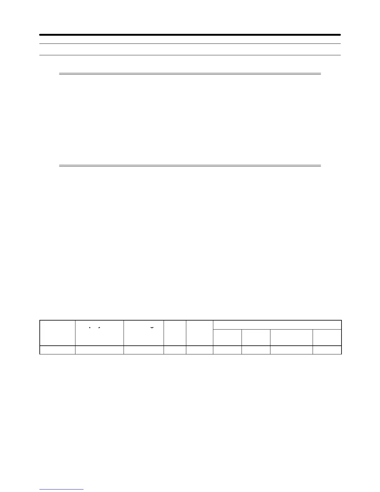
H Setting the PG Pulse Number (F1-01)
Set
the PG (pulse generator or encoder) pulse number in pulses/revolution. Set the number of phase A
or phase B pulses in one motor revolution. This parameter cannot be changed during operation.
Parameter Display name Setting Units Default
Valid access levels*
number
range setting
V/f
Control
V/f with
PG
Open Loop
Vector
Flux
Vector
F1-01 PG Pulses/Rev 0 to 60,000 p/r 1,000 --- Q --- Q
Note Q: Quick-start, Basic, or Advanced
---: Not applicable.
H Setting the PG Rotation Direction (F1-05)
This parameter is used to coordinate the PG’s rotation direction with the motor’s rotation direction; it
cannot be changed during operation.
Generally,
phase A leads when the PG rotates in the clockwise direction
(looking from the input axis).
When
a forward command is input to the inverter
, the motor rotates in the counterclockwise direction
(looking
from the output axis). (These directions may be reversed in
PG-integrated motors or other mo
-
tors.)
Basic Operation Chapter
5