2-39
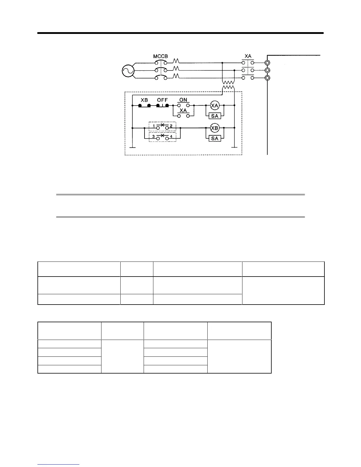
D Power Supply Sequence
200-V class:
Three-phase, 200 to
230 V
AC (50/60 Hz)
400-V class:
Three-phase, 380 to
460 V
AC (50/60 Hz)
Power
supply
Inverter
(See note)
L1 (R)
L2 (S)
L3 (T)
Note Use a transformer with 200- and 400-V outputs for the power supply of the 400-V Inverter.
2-2-5 Wiring Control Circuit Terminals
A
control signal line must be 50 m maximum and separated from power lines. The fre
-
quency reference must be input to the Inverter through twisted-pair wires.
H Wire Size and Round Solderless Terminals
Use thick wires to prevent voltage drops if the wires are long.
D Wires for All Inverter Models
Terminal Terminal
screw
Wire thickness (mm
2
) Type
1 to 11, 13 to 33 M3.5 Stranded wire: 0.5 to 1.25
Single wire: 0.5 to 1.25
Shielded, twisted-pair wire
Shielded,
p
sheath cable
D Round Solderless Terminals for Ground Terminal
Wire thickness
(mm
2
)
Terminal
screw
Size Screw torque
(N S m)
0.5
M3.5
1.25 to 3.5
0.8
0.75 1.25 to 3.5
1.25 1.25 to 3.5
2 2 to 3.5
H Considerations When Wiring Control Circuit Terminals
• Wire control signal lines separately from the main circuit lines and other power lines.
• Wire
control circuit terminals 9, 10, 18, 19, and 20 (contact
outputs) separately from terminals 1 to 8,
21, 22, 23, 25, 26, 27, 33, and 11 to 17.
• Connect shielded wire to terminal 12(G).
• Insulate the shielded areas with tape to prevent contact with other signal lines and equipment.
Installation Chapter
2