5-8
Set
terminal
16’
s gain and bias with H3-06 and H3-07. (Both settings can be changed during operation.)
Parameter Display name Setting Units Default
Valid access levels
number
range setting
V/f
Control
V/f with
PG
Open Loop
Vector
Flux
Vector
H3-06 Terminal 16 Gain 0.0 to
1,000.0
% 100.0 Basic or Advanced
H3-07 Terminal 16 Bias –100.0
to 100.0
% 0.0 Basic or Advanced
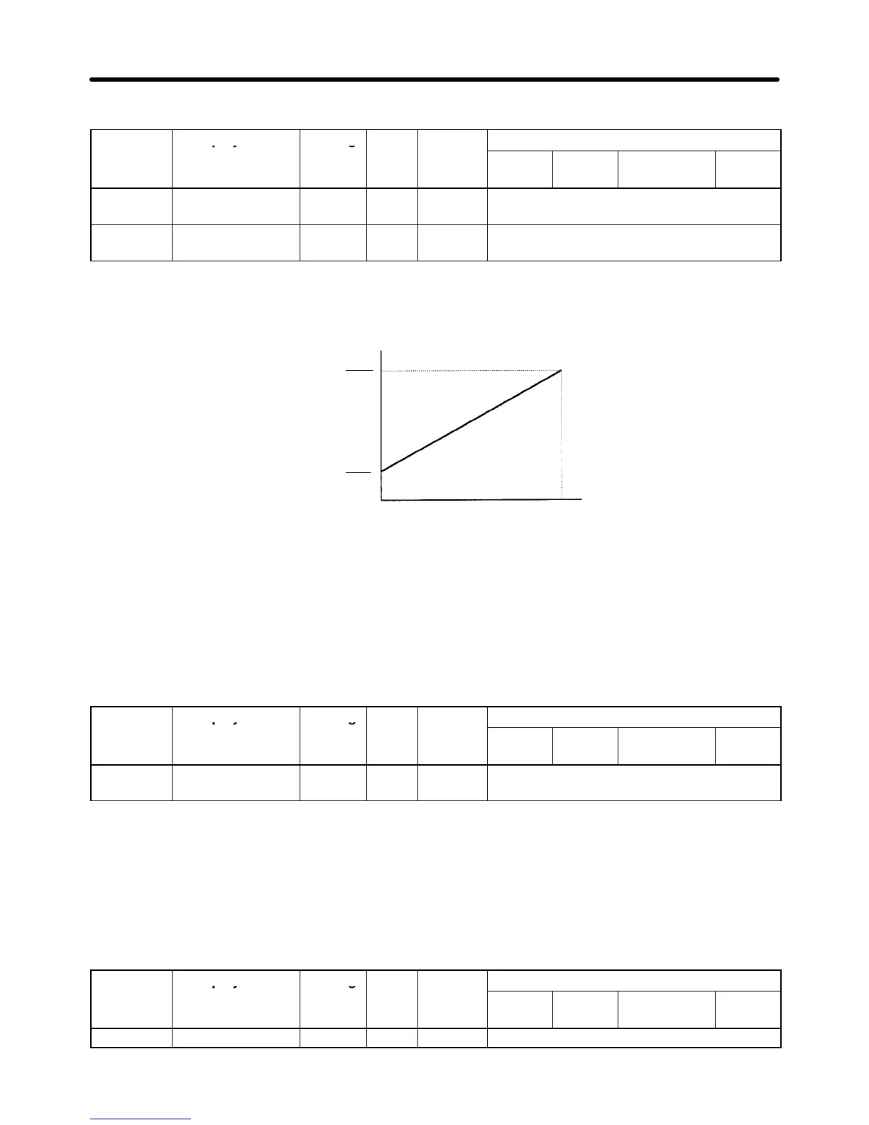
Gain and Bias Chart
10
V
(20 mA)
0 V
(4 mA)
Frequency
reference
Max.frequency
Gain
100
Max.frequency
Bias
100
Note Use the current values shown in parentheses when current input has been selected.
The first-order lag’s digital filter can be set for all three analog inputs (frequency reference (voltage),
frequency reference (current), and multi-function analog input) with parameter H3-12. This setting is
effective when there are sudden changes or noise in the analog input signal. Responsiveness de-
creases as the setting increases.
The filter time constant cannot be changed during operation.
Parameter Display name Setting Units Default
Valid access levels
number
range setting
V/f
Control
V/f with
PG
Open Loop
Vector
Flux
Vector
H3-12 Filter Avg Time 0.00 to
2.00
s 0.00 Advanced
5-1-3 Frequency Reference Settings from Digital Operator
H Selecting the Frequency Reference Source (b1-01)
Parameter b1-01 is used to select the reference source; it cannot be changed during operation.
Parameter Display name Setting Units Default
Valid access levels
number