4-6
4-2-3 Initializing Parameters
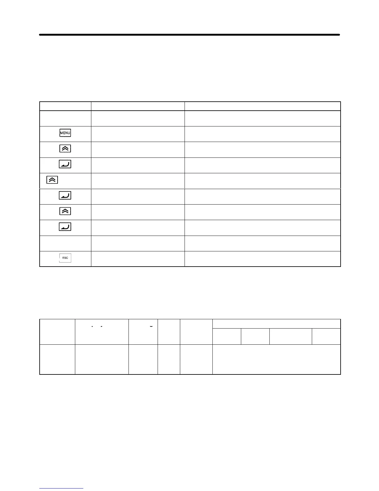
• Initialize the parameters using the following procedure. (Returns to default settings).
• To initialize the parameters, set “2220” in A1-03 (Initialize).
• After
initialization the access level is set to Quick-start (A1-01). The
following table shows the setting
method for Quick-start.
Key sequence Display Explanation
Frequency Ref
U1-01= 0.00 Hz
Frequency reference display.
** Main Menu **
Operation
Displays operation mode.
** Main Menu **
Initialize
Displays initialize mode.
Select Language
English
Puts the Unit in initialize mode.
3 times
Initialize
Select
Displays the Initialize display.
A1-03= 0 ***
Select
Displays the parameter setting for A1-03.
A1-03= 2220
2-wire Initial
Changes the setting to 2-wire Initialization.
Entry Accepted
Writes the set values. “Entry Accepted” is displayed for
approximately 0.5 seconds.
Initialize
Select
Returns to the Initialize display.
** Main Menu **
Initialize
Returns to the initialize mode display.
4-2-4 Setting
Input V
oltage
• Set
the input voltage of the Inverter (E1-01) according to the current voltage. This parameter cannot
be changed during operation.
Parameter Display name Setting Units Default
Valid access levels
number
range setting
V/f
Control
V/f with
PG
Open Loop
Vector
Flux
Vector
E1-01 Input Voltage 155 to
255
(310 to
510)
VAC 200 (400) Quick-start, Basic, or Advanced
Note The
setting range, or the default settings and in indicated in parentheses and indicate values for
the 400-V class.
Trial Operation Chapter
4