8-2
8-1 Protective and Diagnostic Functions
8-1-1 Fault Detection
When
the Inverter detects a fault, the fault code is displayed on the Digital Operator
, the
fault
contact output operates, and the Inverter output is shut OFF causing the motor to
coast
to a
stop. (The stopping method can be selected for some faults, and the selected
stopping method will be used with these faults.)
Before
restarting, reset the error using one of the following procedures. If the run com
-
mand is ON, the reset will be ignored. Turn OFF the run command before resetting.
S Turn ON the fault reset signal.
(A multi-function input (H1-01 to H1-06) must be set to 14 (Fault Reset).)
S Press the RESET Key on the Digital Operator.
S Turn the main circuit power supply off and then on again.
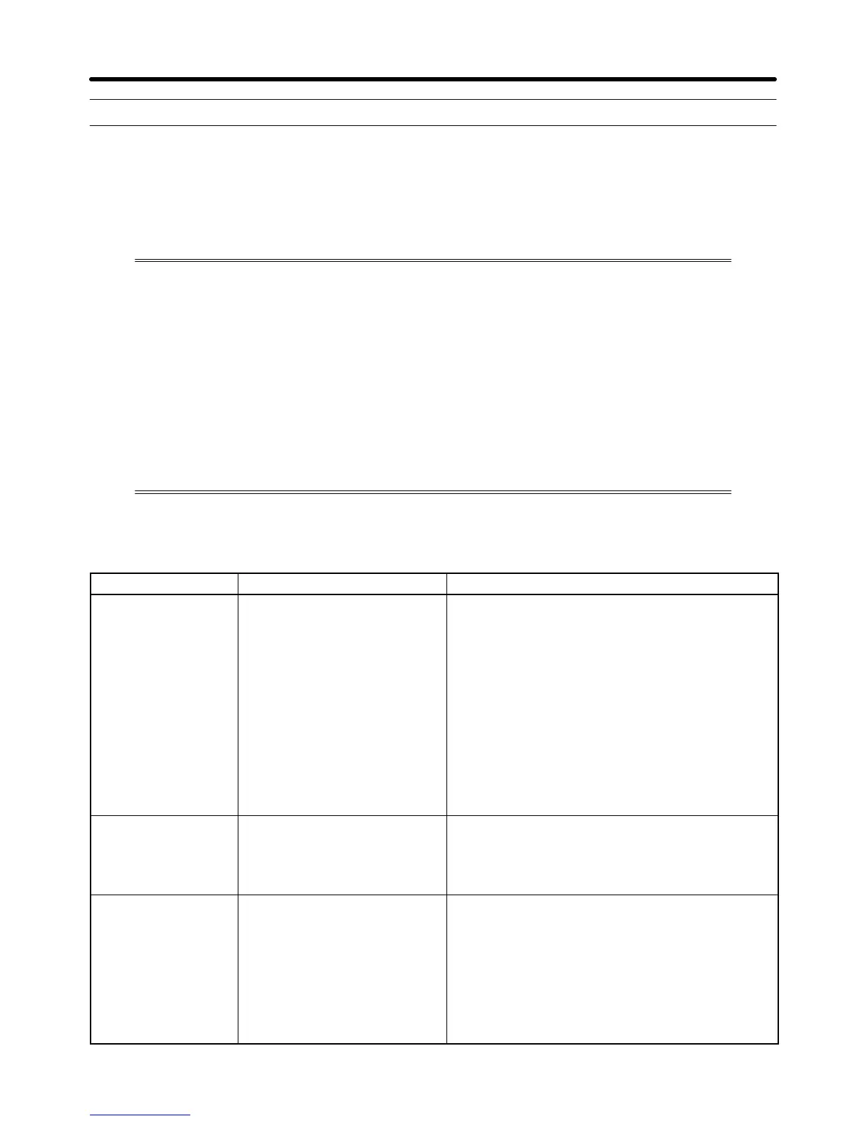
H Fault Displays and Processing
Fault Display Meaning Probable causes and remedies
OC
Overcurrent
The Inverter output current
exceeded the overcurrent
detection level.
• A short-circuit or ground fault occurred at the In-
verter output. (A short or ground fault can be
caused
by motor burn damage, worn insulation,
or
a damaged cable.)
• The
load is too large or the acceleration/decelera
-
tion time is too short.
• A special-purpose motor or motor with a capacity
too large for the Inverter is being used.
• A magnetic switch was switched at the Inverter’s
output.
→ Reset the fault after correcting its cause.
GF
Ground Fault
The ground fault current at the
Inverter’s output exceeded
approximately 80% of the
Inverter’s rated output current.
• A ground fault occurred at the Inverter output.
(A
ground fault can be
caused by motor burn dam
-
age, worn insulation, or a damaged cable.)
→ Reset the fault after correcting its cause.
PUF
DC Bus Fuse Open
The fuse in the main circuit is
blown.
• The
output transistor has
failed because of a short-
circuit or ground fault at the Inverter output.
Check
whether there is a short-circuit between the
following
terminals. A short-circuit will damage the
output transistor:
B1(+3) ↔ T1(U), T2(V), T3(W)
(–) ↔ T1(U), T2(V), T3(W)
→ Replace
the Inverter after correcting the
cause.
Maintenance Operations Chapter
8