4-7
• The following is a setting example for a 200-V class Inverter with an input voltage of 230 V.
Key sequence Display Explanation
** Main Menu **
Operation
Displays initialize mode.
** Main Menu **
Programming
Displays program mode.
Frequency Ref
Terminal
Puts the Unit in program mode.
10 times
Input Voltage
E1-01= 200 VAC
Displays the input voltage setting display.
Input Voltage
200 VAC
Press to change data. (The leading digit will flash).
Input Voltage
200 VAC
Causes the + to flash.
3 times
Input Voltage
230 VAC
Set to “3”
Entry Accepted
The set values are overwritten. “Entry Accepted” is
displayed for approximately 0.5 seconds.
Input Voltage
E1-01= 230 VAC
Returns to the input voltage display. Check that the
data has been updated.
** Main Menu **
Programming
Returns to the program mode display.
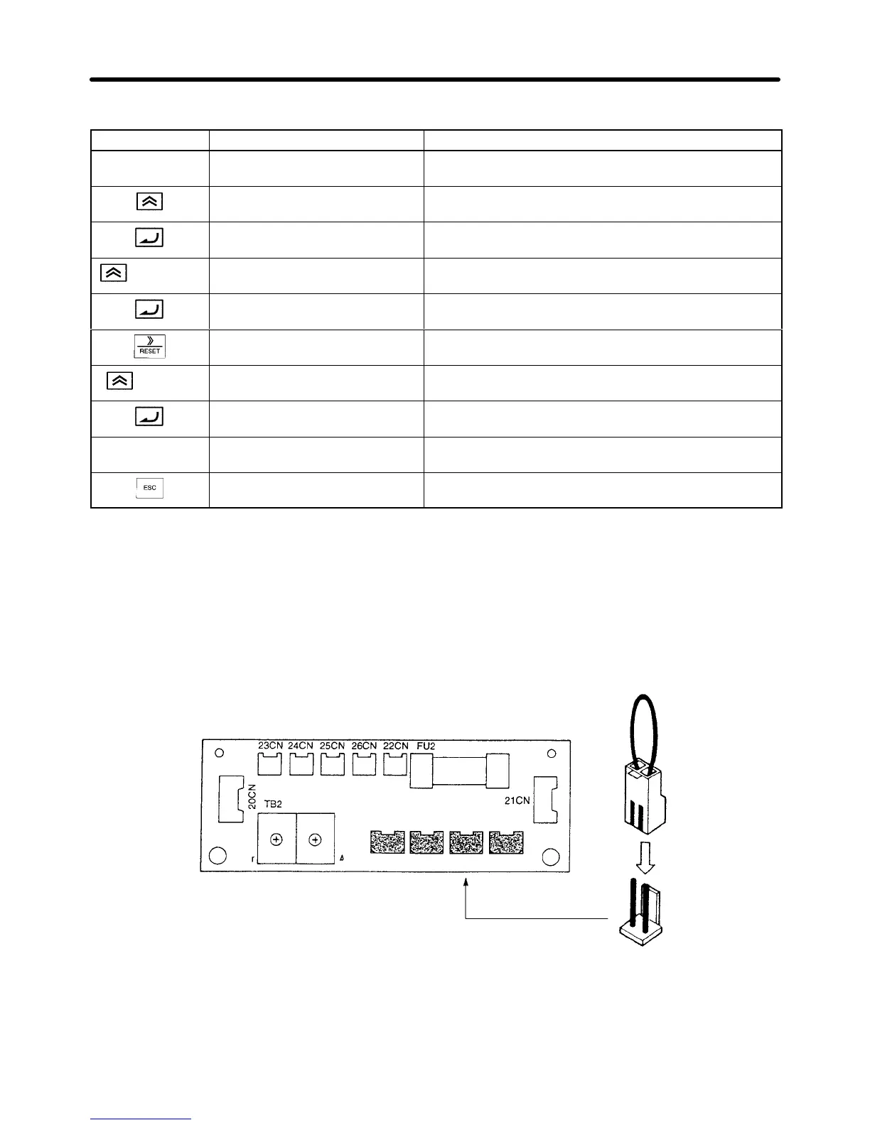
Setting the Power Supply Voltage Short Pin (400-V Class Inverter of
18.5 kW or More)
Set
the power supply voltage short pin when setting the parameter (E1-01). Insert the short pin into the
voltage connector nearest to the actual power supply voltage.
It is factory-set to the 440-V connector when shipped.
380 V 400/415 V 440 V 460 V
Note 1. The above figure is the 400-V class Inverter (18.5 to 45 kW).
Note 2. Be
sure to turn of
f the power supply switch and wait for at least
one minute (three minutes for
models larger than 30 kW) before removing the front panel and setting the pin.
Trial Operation Chapter
4