6-20
position
lock for a long time, select an Inverter with a capacity one rank higher than the capacity of
the motor.
Factor
of 4:
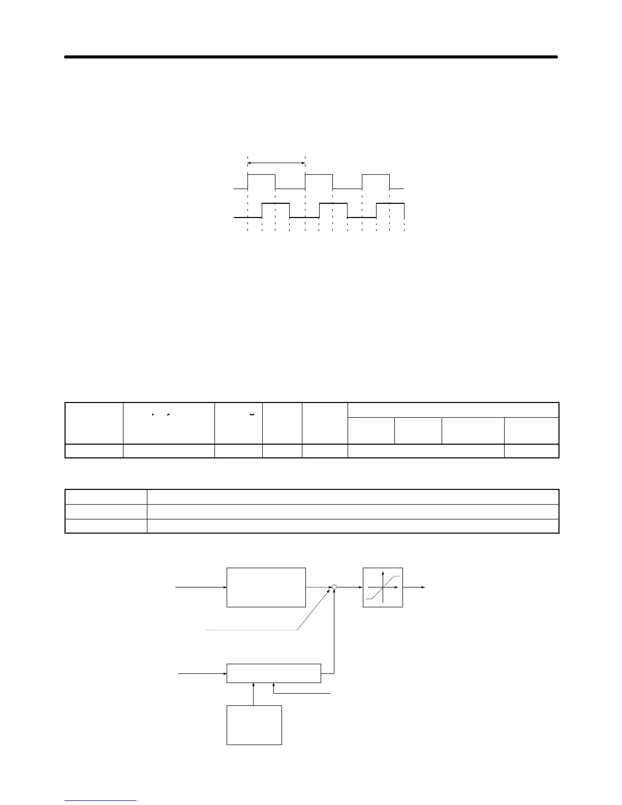
By counting the rising and falling edges of phase A and phase B,
this method has four times the resolution of the PG.
Count
1 pulse
123456789101112
Phase A
Phase B
6-3-4 Torque Control
H Torque Control Function Settings
With
flux vector control, the motor
’
s output torque can be controlled by a torque reference from an ana
-
log
input. Set parameter d5-01 to “1” to select torque control. This
parameter cannot be changed during
operation.
Parameter Display name Setting Units Default
Valid access levels
number
range setting
V/f
Control
V/f with
PG
Open Loop
Vector
Flux
Vector
d5-01 Torq Control Sel 0 or 1 --- 0 Not applicable. Advanced
Settings
Setting Function
0 Speed control (controlled by C5-01 through C5-07)
1 Torque control
The following block diagram shows the operation of torque control.
Torque reference
Torque compensation bias
Speed limit
Torque reference
primary delay filter
(d5-02)
Speed limiting circuit
Speed limit
bias
(d5-05)
Speed feedback
T
orque limit
(L7-01 to L7-04)
Internal torque reference
+
+
+
Advanced Operation Chapter
6