6-2
6-1 Open-loop
V
ector Control
This section summarizes the functions that can be used with open-loop vector control
(vector control without PG feedback) and then provides detailed explanations of the
functions that are specific to open-loop vector control.
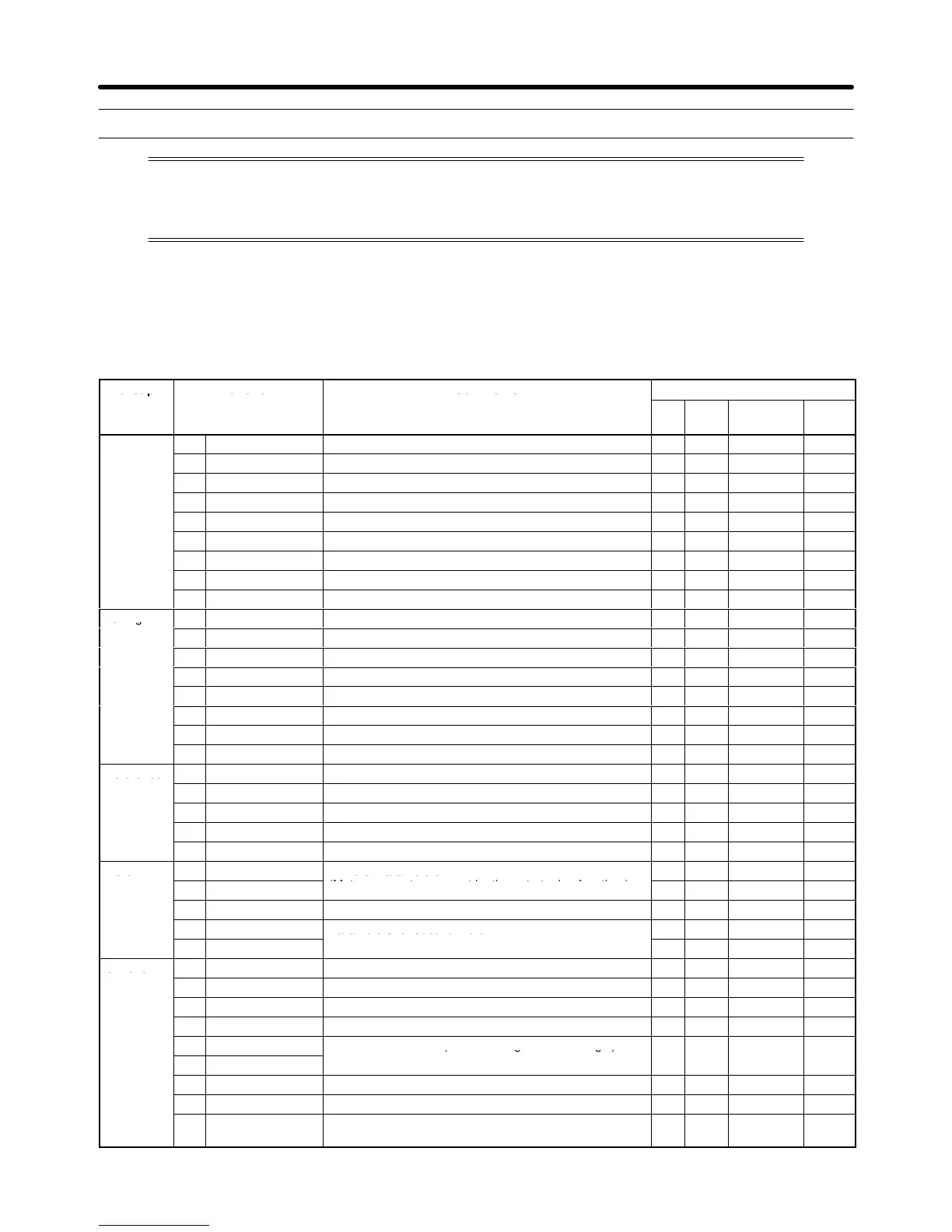
6-1-1 Summary of Open-loop Vector Control Functions
An
“OK” in the control mode column indicates that the parameter can be
changed in that control mode.
The
functions
specific to open-loop vector control are marked with a “
S
” and described in more detail
later in this section.
Group Function Comments
Control
mode
V/f V/f
w/PG
Open-loop
Vector
Flux
Vector
Application
b1 Sequence
Settings such as the reference input method
OK OK OK OK
b2 DC Braking
DC braking function settings
OK OK OK OK
b3
Speed Search
Speed search function settings
OK OK OK OK
b4 Delay Timers T
imer function settings
OK OK OK OK
b5
PID Control
PID control settings
OK OK OK OK
b6
Reference Hold
Accel/deceleration time dwell function settings
OK OK OK OK
b7 ---
Not used. (Can’t be set.)
--- --- --- OK
b8
Energy Saving
Not used. (Can’t be set.)
OK OK --- ---
b9
Zero Servo
Not used. (Can’t be set.)
--- --- --- OK
Tuning
C1 Accel/Decel
Acceleration/deceleration time settings
OK OK OK OK
C2 S-Curve Acc/Dec S-curve characteristics for accel/decel times OK OK OK OK
C3
Motor-Slip Comp
S
Slip compensation function settings
OK OK OK OK
C4 T
orque Comp
S
T
orque compensation function settings
OK OK OK ---
C5 ASR Tuning
Not used. (Can’t be set.)
--- OK --- OK
C6
Carrier Freq
Carrier frequency settings
OK OK OK OK
C7
Hunting Prev
Not used. (Can’t be set.)
OK OK --- ---
C8 Factory Tuning S
Adjustment for open-loop vector control
--- --- OK ---
Reference
d1
Preset Reference
Frequency reference settings (when using Operator)
OK OK OK OK
d2
Reference Limits
Frequency upper and lower limit settings
OK OK OK OK
d3
Jump Frequencies
Prohibited frequency settings
OK OK OK OK
d4 Sequence
Up/Down, Accel/Decel stop hold frequency setting
OK OK OK OK
d5 T
orque Control
Not used. (Can’t be set.)
--- --- --- OK
Motor
E1
V/f Pattern
S
Motor parameters
(M t t t b th t t i f ti )
(Motor parameters are set by the auto-tuning function.)
OK OK OK OK
E3
Control Method 2
Control mode settings for second motor
OK OK OK OK
E4
V/f Pattern 2
Parameters for second motor
OK OK OK OK
E5
Motor Setup 2
OK OK OK OK
Options
F1
PG Option Setup Not used. (Can’t be set.)
--- OK --- OK
F2
AI-14 Setup
Parameter settings for an Analog Command Card
OK OK OK OK
F3
DI-08, 16 Setup
Parameter settings for a Digital Command Card
OK OK OK OK
F4
AO-08, 12 Setup
Parameter settings for an Analog Monitor Card
OK OK OK OK
F5
DO-02 Setup
Not Used. (Do not change these settings.)
--- --- --- ---
F6
DO-08 Setup
o Used ( o ocage esese gs)
F7
PO-36F Setup
Parameter settings for a Pulse Monitor Card
OK OK OK OK
F8
SI-F/G Setup Parameter settings for a SYSMAC BUS Interface Card.
OK OK OK OK
F9
CP-916 Setup
Parameter settings for a CompoBus/D Communications
Card
OK OK OK OK
Advanced Operation Chapter
6