5-46
Note 2. The
parameter settings for E1-04 through E1-10 will be changed automatically when one of
these
patterns
is selected. There are three possible settings for these parameters depending
on
the Inverter
’
s capacity: a 0.4 to 1.5 kW V/f pattern, a 2.2 to 45 kW V/f pattern, and a 55 to
300 kW V/f pattern.
Note 3. The
characteristics for these patterns are
shown in the diagrams on pages
5-25 through
5-27.
H Setting a User-defined V/f Pattern (Setting “F”)
Parameters
E1-04 through E1-10 can be set by the user when E1-03 has
been set to “F
.” Refer to page
5-28 for details on setting these parameters.
5-5-3 PG Speed Control Card Settings
H Available PG Speed Control Cards
There are 4 types of PG Speed Control Cards, but only 2 types can be used with V/f control.
3G3FV-PPGA2: Phase-A (single) pulse input, input for open collector
3G3FV-PPGD2: Phase-A (single) pulse input, line driver inputs
Select
the Card according to the application and install it in the Inverter
as described in
2-2-6 Installing
and Wiring PG Speed Control Cards
.
H Setting the PG Pulse Number (F1-01)
Set
the PG (pulse generator or encoder) pulse number in pulses/revolution. Set the number of phase A
or phase B pulses in one motor revolution. This parameter cannot be changed during operation.
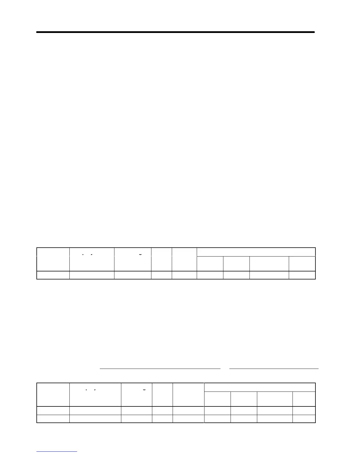
Parameter Display name Setting Units Default
Valid access levels*
number
range setting
V/f
Control
V/f with
PG
Open Loop
Vector
Flux
Vector
F1-01 PG Pulses/Rev 0 to 60,000 p/r 1,000 --- Q --- Q
Note Q: Quick-start, Basic, or Advanced
---: Not applicable.
H Setting the Number of PG Gear Teeth (F1-12 and F1-13)
When
“V/f control with PG feedback” is used, the motor can be operated even if there are gears between
the motor and PG because the responsiveness is lower than it is with vector control.
Set
the number of teeth on the gears if there are gears between the motor and PG. The motor
’
s speed
will be calculated within the Inverter using the following equation:
Motor speed (r+min) )
Number of pulses input from the PG 60
Number of PG pulses (F1–01)
Number of gear teeth 2 (F1–13)
Number of gear teeth 1 (F1–12)
Parameter Display name Setting Units Default
Valid access levels
1
number
range setting
V/f
Control
V/f with
PG
Open Loop
Vector
Flux
Vector
F1-12 PG # Gear Teeth1 0 to 1,000 --- 0 --- A --- ---
F1-13 PG # Gear Teeth2 0 to 1,000 --- 0 --- A --- ---
Basic Operation Chapter
5