5-44
5-5 V/f Control with PG
With
V/f control with PG, the user must set the motor parameters, V/f pattern, PG Control
Card settings, and then adjust the speed control loop’s gain.
5-5-1 Setting the Motor Parameters
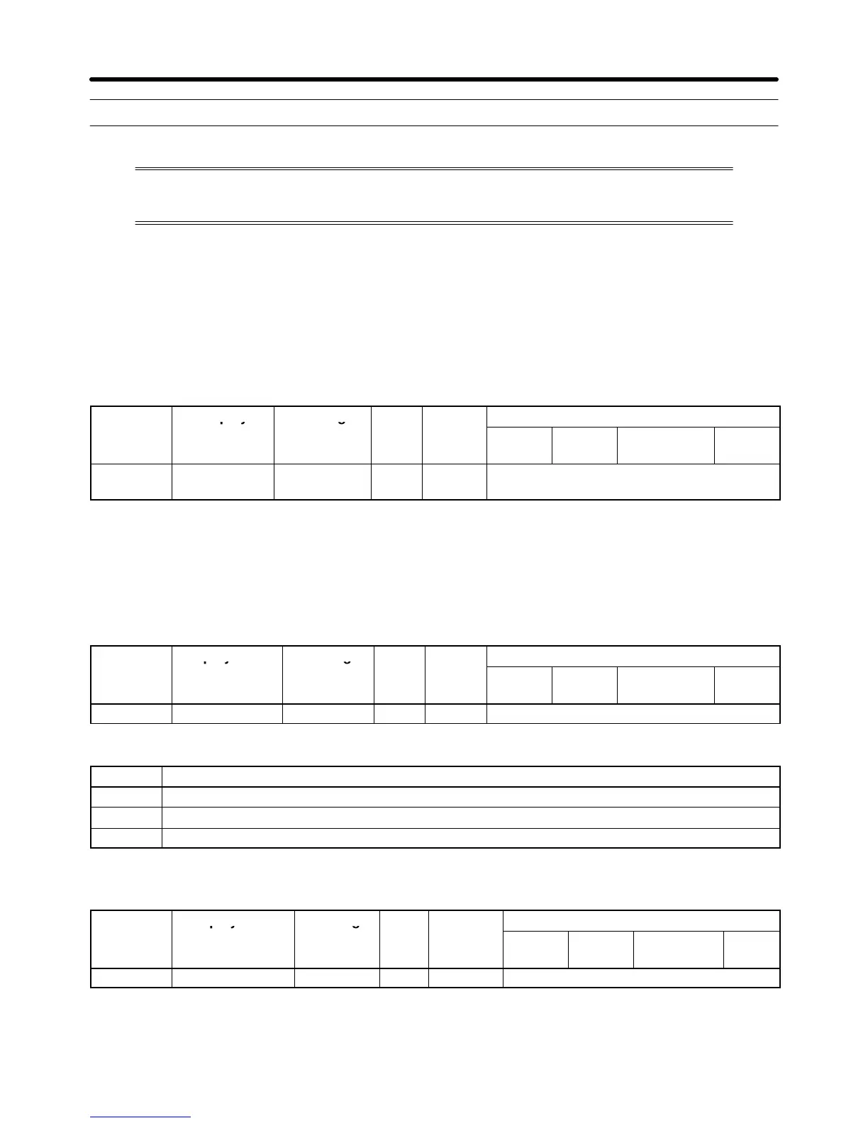
H Inverter Input Voltage Setting (E1-01)
Set
the Inverter
’
s input voltage (E1-01) to match the power
supply voltage; it cannot be changed during
operation. This setting is used as the reference value for functions such as the protection functions.
Parameter Display Setting Units Default
Valid access levels
number
range setting
V/f
Control
V/f with
PG
Open Loop
Vector
Flux
Vector
E1-01 Input Voltage 155 to 255
(310 to 510)
VAC 200
(400)
Quick-start, Basic, or Advanced
Note The voltage settings shown in parentheses are the values for the 400-V class.
H Motor Selection and Rated Current Setting (E1-02 and E2-01)
Set
the type of motor being used with the motor selection parameter (E1-02). This setting is a reference
for the protection functions. This parameter cannot be changed during operation.
Parameter Display name Setting Units Default
Valid access levels
number
range setting
V/f
Control
V/f with
PG
Open Loop
Vector
Flux
Vector
E1-02 Motor Selection 0 to 2 --- 0 Quick-start, Basic, or Advanced
E1-02 Settings
Setting Function
0 Standard fan-cooled motor (general-purpose motor)
1 Standard blower-cooled motor (inverter-exclusive motor)
2 Special motor (special vector control motor)
Set
parameter (E2-01) to rated current (A)
shown on the motor
’
s nameplate. This parameter cannot be
changed during operation.
Parameter Display name Setting
Valid access levels
number
range
1
setting
2
V/f
Control
V/f with
PG
Open Loop
Vector
Flux
Vector
E2-01 Motor Rated FLA 10 to 200% A (Note 2) Quick-start, Basic, or Advanced
Note 1. The setting range is 10 to 200% of the Inverter’s rated output current.
Note 2. The default setting depends upon the type of Inverter.
Basic Operation Chapter
5