5-50
5-5-4 Speed Loop (ASR) Structure
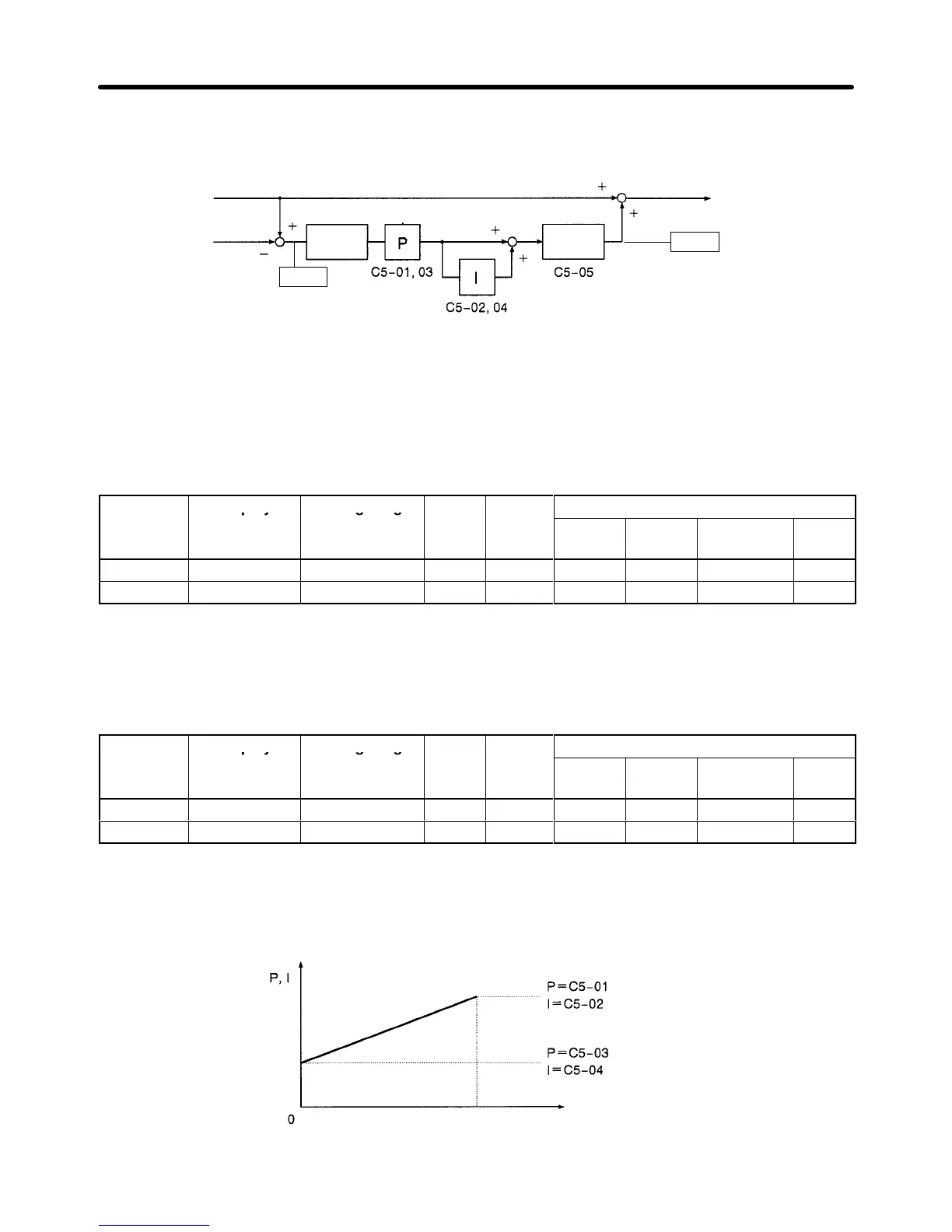
The following block diagram shows the structure of the speed loop.
Frequency
reference
Detected
speed
Change
limiter
Limiter
Output frequency
U1-21
U1-22
H Gain Settings
When
using
“V/f control with PG feedback,” set the gain at the minimum frequency and maximum fre
-
quency.
D Max. Frequency Gain Settings (C5-01 and C5-02)
Set ASR proportional gain 1 (C5-01) and ASR integral time 1 (C5-02) at the maximum frequency.
Parameter Display Setting range Units Default
Valid access levels*
number
setting
V/f
Control
V/f with
PG
Open Loop
Vector
Flux
Vector
C5-01
ASR P Gain 1
0.00 to 300.00 Factor 0.20 --- B --- B
C5-02 ASR I Time 1 0.000 to 10.000 s 0.200 --- B --- B
Note B: Basic or Advanced
---: Not applicable.
D Min. Frequency Gain Settings (C5-03 and C5-04)
Set ASR proportional gain 2 (C5-03) and ASR integral time 2 (C5-04) at the minimum frequency.
Parameter Display Setting range Units Default
Valid access levels*
number
setting
V/f
Control
V/f with
PG
Open Loop
Vector
Flux
Vector
C5-03
ASR P Gain 2
0.00 to 300.00 Factor 0.02 --- B --- B
C5-04 ASR I Time 2 0.000 to 10.000 s 0.050 --- B --- B
Note B: Basic or Advanced
---: Not applicable.
The
following graph shows how the proportional gain and integral time are calculated from parameters
C5-01 through C5-04.
Motor speed (Hz)
E1-04
(Max. frequency)
Basic Operation Chapter
5