range setting
V/f
Control
V/f with
PG
Open Loop
Vector
Flux
Vector
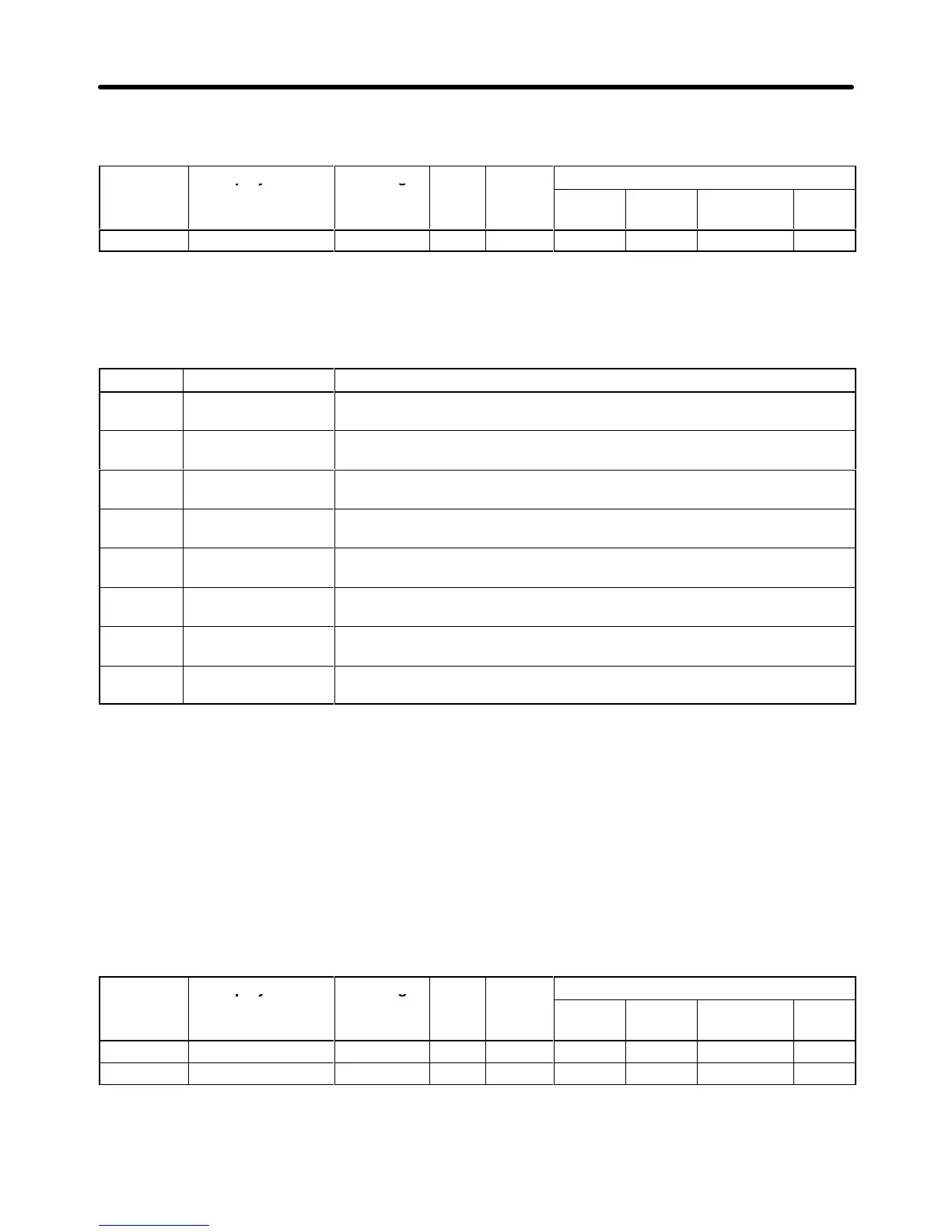
F1-04 PG Deviation Sel 0 to 7 --- 3 --- B --- B
Note B: Basic or Advanced
---: Not applicable.
Settings
Setting Stopping method Function
0 Ramp to Stop
(C1-02)/Fault
Detect
when deviation occurs with the frequence reference matching
(within
the L4-02 detection range) the output frequency.
1 Coast to Stop/Fault Detect
when deviation occurs with the frequence reference matching
(within
the L4-02 detection range) the output frequency.
2 Fast Stop
(C1-09)/Fault
Detect
when deviation occurs with the frequence reference matching
(within
the L4-02 detection range) the output frequency.
3 Continue/Alarm
Only
Detect
when deviation occurs with the frequence reference matching
(within
the L4-02 detection range) the output frequency.
4 Ramp to Stop
(C1-02)/Fault
Detect
when deviation occurs with the frequence reference matching
(within
the L4-02 detection range) the motor speed (PG feedback).
5 Coast Stop/Fault Detect
when deviation occurs with the frequence reference matching
(within
the L4-02 detection range) the motor speed (PG feedback).
6 Fast Stop
(C1-09)/Fault
Detect
when deviation occurs with the frequence reference matching
(within
the L4-02 detection range) the motor speed (PG feedback).
7 Continue/Alarm
Only
Detect
when deviation occurs with the frequence reference matching
(within
the L4-02 detection range) the motor speed (PG feedback).
Note 1. In
order to detect faulty contacts, and so on, inserted at the Inverter output side, select
detec
-
tion when the frequency reference matches the output frequency.
Note 2. The detection conditions vary as shown below depending on the software version. In Ver.
VSG101114 and later versions, both functions are provided.
VSG101043 and earlier software: Set values 0 to 3.
VSG101113 software: Set values 4 to 7.
Parameter
F1-10 sets the PG speed deviation detection level as a percentage of the maximum output
frequency. Parameter F1-11 sets the length of time that the difference between the motor speed and
reference
speed must exceed the PG speed deviation detection level
in order to generate a PG speed
deviation fault (DEV).
Parameter Display name Setting Units Default
Valid access levels*
number