6-39
• Increase the setting in C7-02 if vibration occurs when operating with a light load.
(If the setting is increased too much, the current can fall to the point where stalling occurs.)
• Decrease the setting in C7-02 if stalling occurs.
• Disable the hunting-prevention function (C7-01 = 0) if high responsiveness is more important than
suppressing vibration.
6-4-4 Setting Motor Parameters
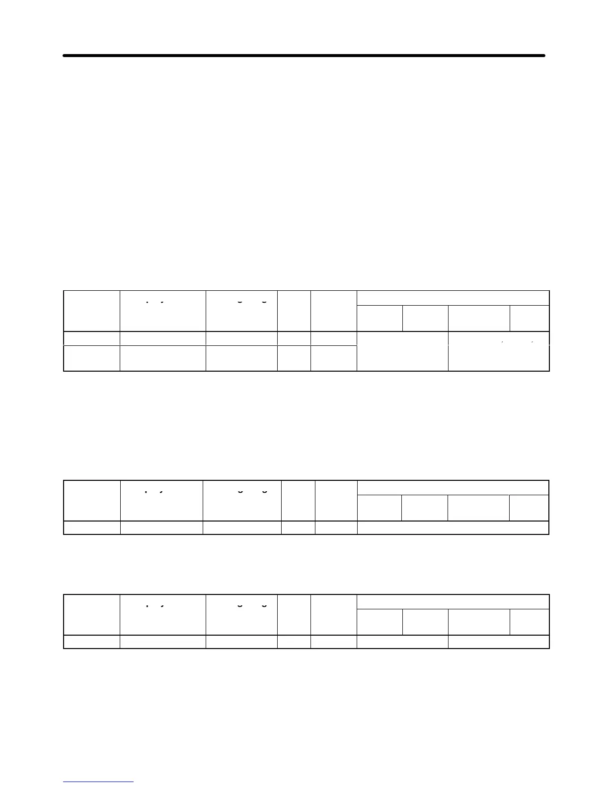
The motor parameters other than the V/f pattern parameters are described below:
Calculate
the rated slip (E2-02) from the value shown on the motor
’
s nameplate with the following equa
-
tion and set this value.
Rated slip = rated frequency (Hz) – rated speed (r/min) × number of poles/120
Set
the no-load current (E2-03) at the rated voltage and rated frequency
. Normally this value isn’t shown
on the motor’s nameplate, so it might be necessary to contact the motor manufacturer.
Parameter Display name Setting range Units Default
Valid access levels
number
setting*
V/f
Control
V/f with
PG
Open Loop
Vector
Flux
Vector
E2-02 Motor Rated Slip 0.00 to 20.00 Hz 2.90
Advanced Quick Start, Basic,
E2-03 No-Load Current 0.00 to 2.90
(see note 2)
A 1.20
or Advanced
Note 1. The default setting depends upon the type of Inverter.
(The table shows the default settings for 200-V class, 0.4-kW Inverters.)
Note 2. The setting range is between 0.00 and 0.1 less than the Inverter’s rated current.
Note 3. These settings are used as reference values for the motor slip compensation function.
Set the motor’s terminal resistance (phase to phase) in parameter E2-05. Normally this value isn’t
shown on the motor’s nameplate, so it might be necessary to contact the motor manufacturer.
Parameter Display name Setting range Units Default
Valid access levels
number
setting
V/f
Control
V/f with
PG
Open Loop
Vector
Flux
Vector
E2-05 Term Resistance 0.000 to 65.000 Ω 9.842 Advanced
Note 1. The default setting depends upon the type of Inverter.
(The table shows the default settings for 200-V class, 0.4-kW Inverters.)
Note 2. This setting is used as a reference value for the torque compensation function.
Parameter Display name Setting range Units Default
Valid access levels
number
setting*
V/f
Control
V/f with
PG
Open Loop
Vector
Flux
Vector
E2-10 Tcomp Iron Loss 0 to 65535 W 14 Advanced Not applicable.
Note 1. The default setting varies with the Inverter’s capacity. The above setting applies to 200-V
class, 0.4-kW Inverters.
Note 2. Set the iron core loss in 1-W increments. The default setting does not normally need to be
changed.
Note 3. The set value is used as the reference value for the torque compensation function.
Advanced Operation Chapter
6