5-24
5-3-2 V/f Pattern Selection (E1-03)
Set the V/f pattern with parameter E1-03. This parameter cannot be changed during operation.
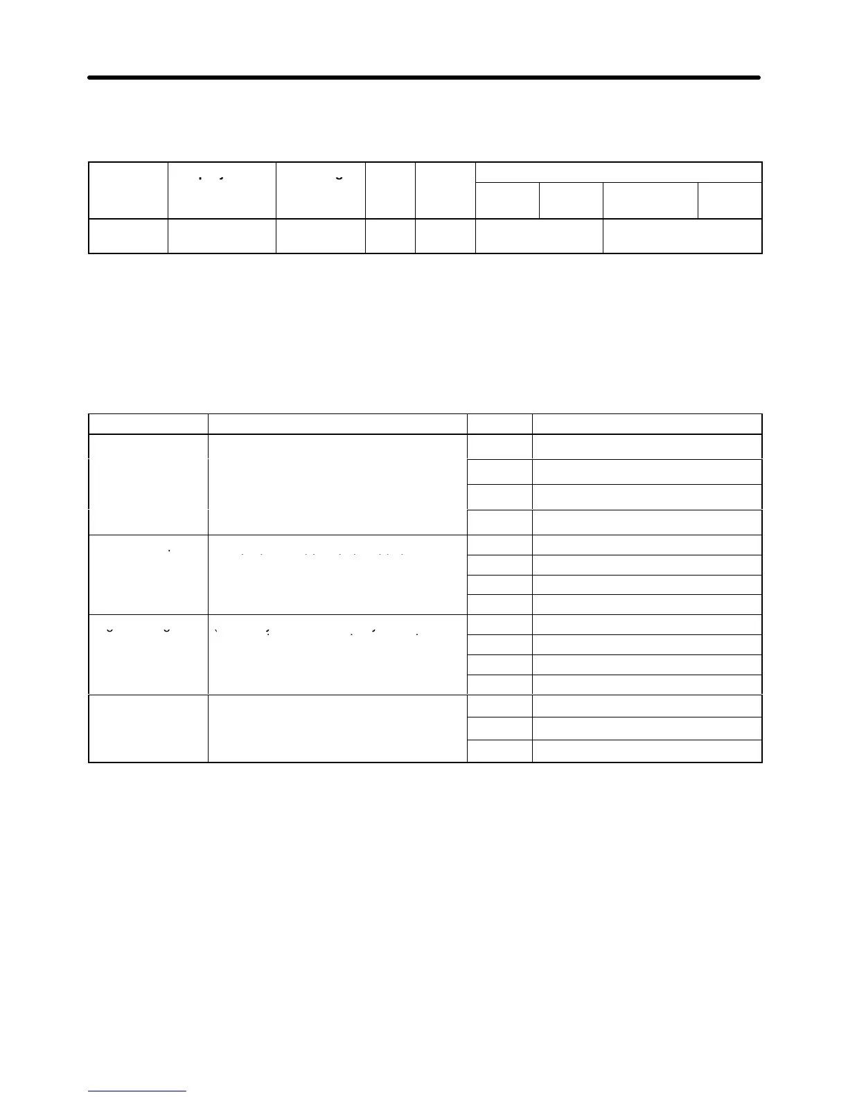
Parameter Display name Setting Units Default
Valid access levels
number
range setting
V/f
Control
V/f with
PG
Open Loop
Vector
Flux
Vector
E1-03 V/f Selection 0 to F --- F Quick-start, Basic,
or Advanced
Not applicable.
The
V/f pattern settings can be divided into two categories: the 15 preset patterns (settings 0 through E)
and
custom user-set patterns (setting F). The factory default setting for E1-03 is “F” (user-defined V/f
pattern), but the contents of this setting are actually the same as setting “1.”
H Selecting a Preset V/f Pattern (Settings “0” through “E”)
Refer to the following table when selecting one of the 15 preset patterns.
Characteristics Applications Setting Specifications
General-purpose These patterns are for general-purpose
roughly proportional relationship
2 60 Hz, Voltage saturation at 50 Hz
between the rotational speed and load,
such as in straight-line conveyors.
3 72 Hz, Voltage saturation at 60 Hz
Variable torque Use these patterns when there is a
quadratic or cubic relationship between
5 50 Hz, quadratic
the rotational speed and load, such as
.
7 60 Hz, quadratic
High starting (Normally it isn’t necessary to use these
8 50 Hz, low starting torque
patterns because starting torque is
ensured by automatic torque boost
9 50 Hz, high starting torque
ensured by automatic torque boost
A 60 Hz, low starting torque
b 60 Hz, high starting torque
High-speed
These patterns are for applications that
must rotate at frequencies greater than
C 90 Hz, Voltage saturation at 60 Hz
operation must rotate at frequencies greater than
d 120 Hz, Voltage saturation at 60 Hz
frequencies greater than 60 Hz.
E 180 Hz, Voltage saturation at 60 Hz
Note 1. Select a high starting torque V/f pattern only in the following cases:
S The wiring distance between the Inverter and motor is relatively large (greater than 150 m).
S A large torque is required at startup (such as heavy axis loads).
S An AC or DC reactor is connected to the Inverter’s input or output.
Note 2. The
parameter settings for E1-04 through E1-10 will be changed automatically when one of
these
patterns
is selected. There are three possible settings for these parameters depending
on
the Inverter
’
s capacity: a 0.4 to 1.5 kW V/f pattern, a 2.2 to 45 kW V/f pattern, and a 55 kW
V/f pattern.
Note 3. The
characteristics for these patterns are shown in the diagrams on the following pages. The
voltages in these graphs are for 200-V class Inverters. Double the voltage for 400-V class
Inverters.
Basic Operation Chapter
5