3-25
3-5 Program Mode
The
Inverter parameters can be set in program mode. The parameters which can be dis
-
played
and changed depend on the access level and control mode that are being used.
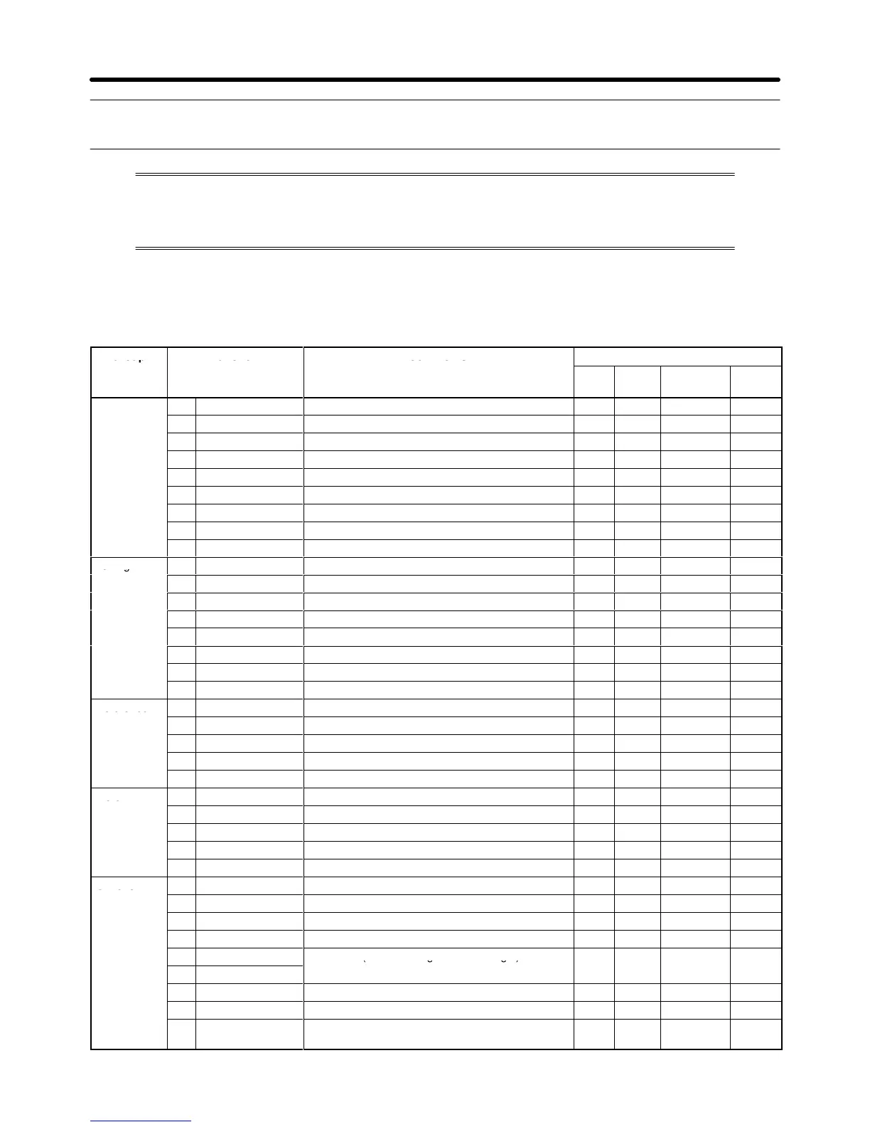
Refer to the following table to determine if a parameter can be changed.
S Parameter Groups
An
“OK” in the control mode column indicates that the parameter can be
changed in that control mode.
Group Function Comments
Control
mode
V/f V/f
w/PG
Open-loop
Vector
Flux
Vector
Application
b1 Sequence
Settings such as the reference input method
OK OK OK OK
b2 DC Braking
DC braking function settings
OK OK OK OK
b3
Speed Search
Speed search function settings
OK OK OK OK
b4 Delay Timers T
imer function settings
OK OK OK OK
b5
PID Control
PID control settings
OK OK OK OK
b6
Reference Hold
Accel/deceleration time dwell function settings
OK OK OK OK
b7
Droop Control
Droop control (speed drop) settings
--- --- --- OK
b8
Energy Saving
T
erminal input energy-saving control settings
OK OK --- ---
b9
Zero Servo
Stop in the position loop
--- --- --- OK
Tuning
C1 Accel/Decel
Acceleration/deceleration time settings
OK OK OK OK
C2 S-Curve Acc/Dec S-curve characteristics for accel/decel times OK OK OK OK
C3
Motor-Slip Comp
Slip compensation function settings
OK OK OK OK
C4 T
orque Comp
T
orque compensation function settings
OK OK OK ---
C5 ASR Tuning
Speed control loop parameter settings
--- OK --- OK
C6
Carrier Freq
Carrier frequency settings
OK OK OK OK
C7
Hunting Prev
Hunting prevention function for V/f control
OK OK --- ---
C8 Factory Tuning
Adjustment for open-loop vector control
--- --- OK ---
Reference
d1
Preset Reference
Operator frequency reference settings
OK OK OK OK
d2
Reference Limits
Frequency upper and lower limit settings
OK OK OK OK
d3
Jump Frequencies
Prohibited frequency settings
OK OK OK OK
d4 Sequence
Hold for analog frequency reference
OK OK OK OK
d5 T
orque Control
Parameter settings for torque control
--- --- --- OK
Motor
E1
V/f Pattern
Sets the motor
’s V/f characteristics. OK OK OK OK
E2
Motor Setup
Sets the motor parameters.
OK OK OK OK
E3
Control Method 2
Sets the control method of motor 2.
OK OK OK OK
E4
V/f Pattern 2
Sets the V/f pattern of motor 2.
OK OK OK OK
E5
Motor Setup 2
Motor setup for motor 2.
OK OK OK OK
Options
F1
PG Option Setup
Parameter settings for a PG Card
--- OK --- OK
F2
AI-14 Setup
Parameter settings for an Analog Reference Card
OK OK OK OK
F3
DI-08, 16 Setup
Parameter settings for a Digital Reference Card
OK OK OK OK
F4
AO-08, 12 Setup
Parameter settings for an Analog Monitor Card
OK OK OK OK
F5 Not used (DO-02)
Not Used. (Do not change these settings.)
--- --- --- ---
F6 Not used (DO-08)
o Used ( o ocage esese gs)
F7
PO-36F Setup
Parameter settings for a Pulse Monitor Card.
OK OK OK OK
F8
SI-F/G Setup
SYSMAC BUS Interface card setup.
OK OK OK OK
F9
CP-916 Setup
CompoBus/D (DeviceNet) communications card
setup.
OK OK OK OK
Preparing for Operation Chapter
3