3-26
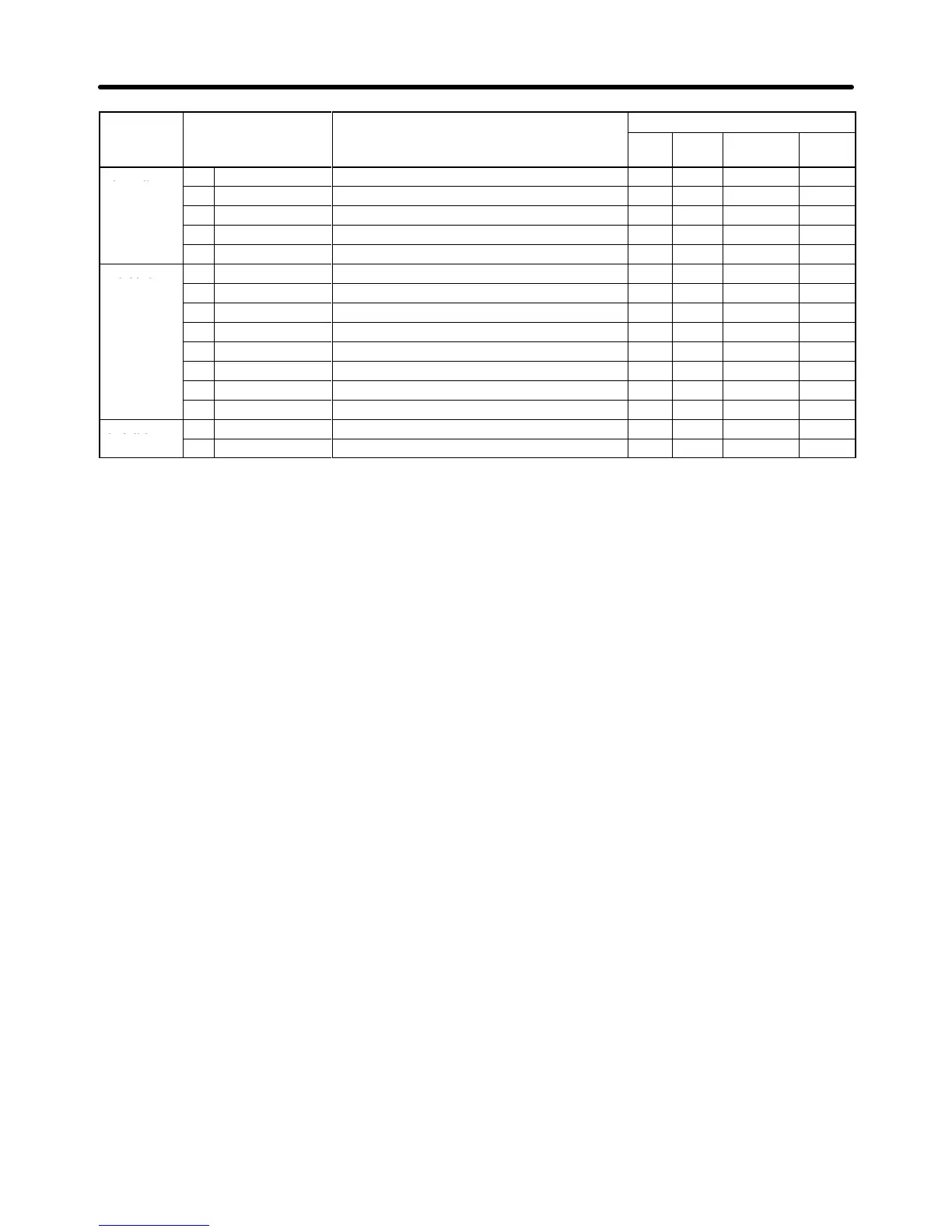
Group Control
mode
CommentsFunctionGroup
Flux
Vector
Open-loop
Vector
V/f
w/PG
V/f
CommentsFunction
Terminal
H1
Digital Inputs
Function selection for multi-function inputs
OK OK OK OK
H2
Digital Outputs
Function selection for multi-function outputs
OK OK OK OK
H3
Analog Inputs
Function selection for analog inputs
OK OK OK OK
H4
Analog Outputs
Function selection for analog outputs
OK OK OK OK
H5
Serial Com Setup
Not Used. (Do not change these settings.)
--- --- --- ---
Protection
L1
Motor Overload Overload protection settings and selection
OK OK OK OK
L2 PwrLoss Ridethru
Selects the power-loss processing method.
OK OK OK OK
L3
Stall Prevention
Stall prevention settings and selection
OK OK OK OK
L4
Ref Detection
Frequency detection settings and selection
OK OK OK OK
L5
Fault Restart
Fault restart function settings
OK OK OK OK
L6 T
orque Detection
Overtorque detection settings and selection
OK OK OK OK
L7 T
orque Limit
T
orque limit settings (vector control only)
--- --- OK OK
L8
Hdwe Protection
Overheating and phase loss protection settings
OK OK OK OK
Operator
o1
Monitor Select
Selects the display and setting methods.
OK OK OK OK
o2 Key Selections
Key function selection and other parameters
OK OK OK OK
S Setting Parameters in Program Mode
The parameters that can be displayed and changed will vary depending on the access
level that has
been set.
In
the Quick-start level, the first parameter (b1-01) will be displayed when the Enter
Key is pressed at the
program
mode display
. In the Basic level, the first function (b1) will be displayed when the Enter Key is
pressed
at the program mode display
. In the Advanced level, the first group (b) will
be displayed when
the Enter Key is pressed at the program mode display.
For setting examples, refer to
Setting Parameters in Each Access Level
on page 3-6.
Preparing for Operation Chapter
3