6-111
• If
the
output torque at low speed is a problem (i.e., a heavy load is connected at low speed), set the
parameter L8-18 to 1 and the parameter L8-19 to 0.
Note 1. Do
not set both parameters (L8-17 and L8-19) to 0, otherwise the Inverter may be damaged.
In
that case, use a higher rank Inverter with parameter L8-17 set to 0 and parameter L8-19 set
to 1.
Note 2. Use
a higher rank Inverter or set parameter C6-01 (Carrier Freq
Max) to 2 kHz if a high load is
continuously connected at low speed in flux vector control mode.
Settings for L8-17
Setting Function
0 Disabled. (The carrier frequency is not reduced at low speed.)
1 Enabled. (The carrier frequency is reduced at low speed.)
2
For factory adjustment. (Do not use.)
3
Settings for L8-19
Setting Function
0 Disabled. (The OL2 detection level is not reduced at low speed.)
1 Enabled (The OL2 detection level is reduced at low speed.)
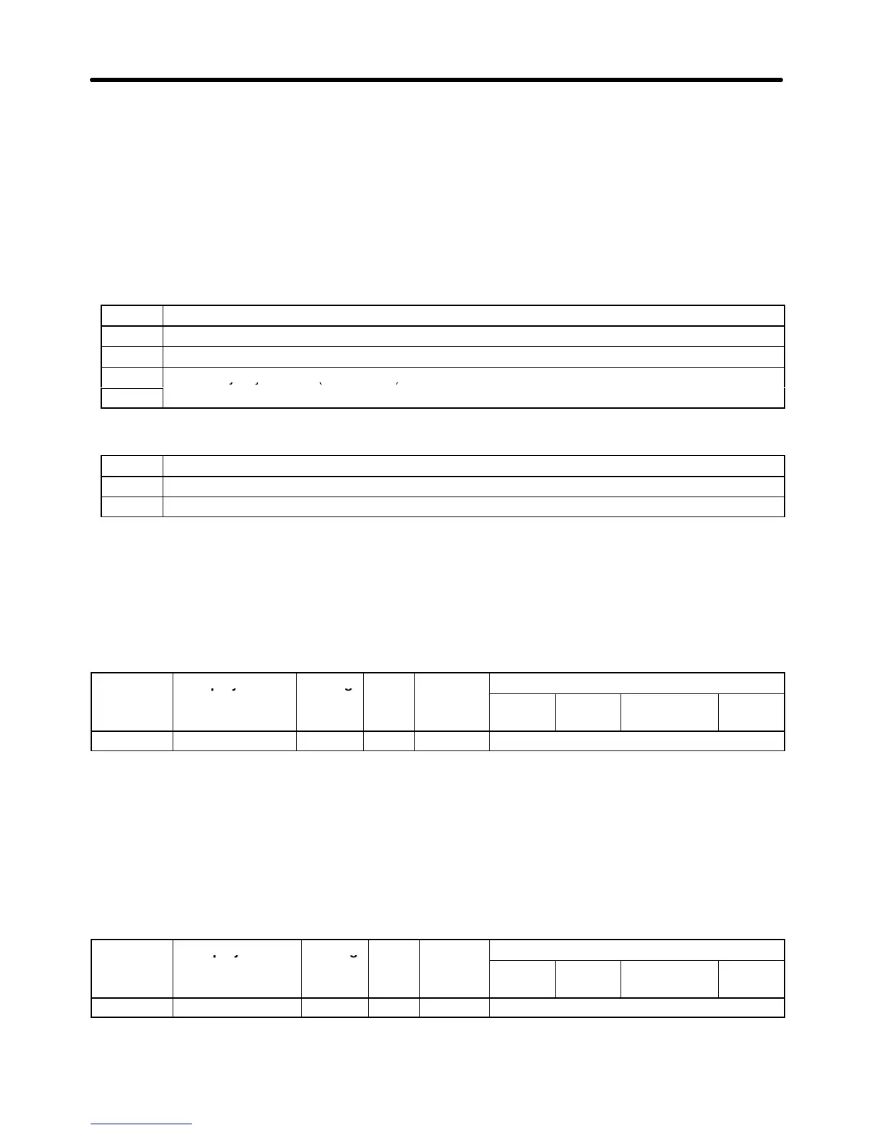
6-5-9 Operator Parameters: o
H Operator Display Selection (o1)
Parameter Display name Setting Units Default
Valid access levels
number
range setting
V/f
Control
V/f with
PG
Open Loop
Vector
Flux
Vector
o1-01 User Monitor Sel 4 to 38 --- 6 Basic or Advanced
Note This parameter can be changed during operation.
• In
operation mode, the frequency reference, output
frequency
, output current, and output voltage can
be
monitored immediately if the default settings are being used. One of these four
values, the output
voltage,
can be changed to a dif
ferent value. When you want to monitor a value other than the output
voltage, set that value’s number in parameter o1-01.
• Use
the last two digits from the “U1 Monitor” list (U1-
) to select a value. Refer to page
3-12 for a
table listing all of these U1 settings.
Parameter Display name Setting Units Default
Valid access levels
number
range setting
V/f
Control
V/f with
PG
Open Loop
Vector
Flux
Vector
o1-02 Power-On Monitor 1 to 4 --- 1 Basic or Advanced
Note This parameter can be changed during operation.
Advanced Operation Chapter
6