2-33
Note The carrier frequency setting range varies depending on the Inverter capacity.
200-V class, 18.5 kW max.; 400-V class, 30 kW max.: 0.4 to 15.0 kHz
200-V class, 22 to 75 kW; 400-V class, 37 to 160 kW: 0.4 to 10.0 kHz
400-V class, 185 to 300 kW: 0.4 to 2.5 kHz
D Single-phase Motors Cannot Be Used
The Inverter is not suited for the variable speed control of single-phase motors.
Single-phase
motors are either capacitor start motors or split-phase start
motors. (The method for de
-
termining
rotation direction at startup is dif
ferent.) If a capacitor start motor is used, the capacitor may be
damaged
by a sudden electric discharge caused by Inverter output. If a split-phase start motor is used,
the starting coil may burn because the centrifugal switch does not operate.
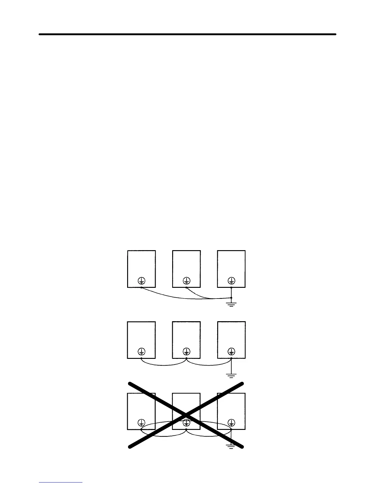
H Ground Wiring
• Always
use the ground terminal of the 200-V Inverter with a ground resistance of less than 100
Ω
and
that of the 400-V Inverter with a ground resistance of less than 10 Ω.
• Do not share the ground wire with other devices such as welding machines or power tools.
• Always use a ground wire that complies with technical standards on electrical equipment and mini-
mize the length of the ground wire.
Leakage
current flows through the Inverter
. Therefore, if the distance between the ground electrode
and
the ground terminal is too long, potential on the ground terminal of the Inverter will become unsta
-
ble.
• When using more than one Inverter, be careful not to loop the ground wire.
Installation Chapter
2