6-21
H Torque Reference Settings
• Set multi-function analog input (terminal 16) or frequency reference current input (terminal 14) to
torque reference. The torque reference value cannot be set with the Digital Operator.
Parameter Display name Setting Units Default
Valid access levels
number
range setting
V/f
Control
V/f with
PG
Open Loop
Vector
Flux
Vector
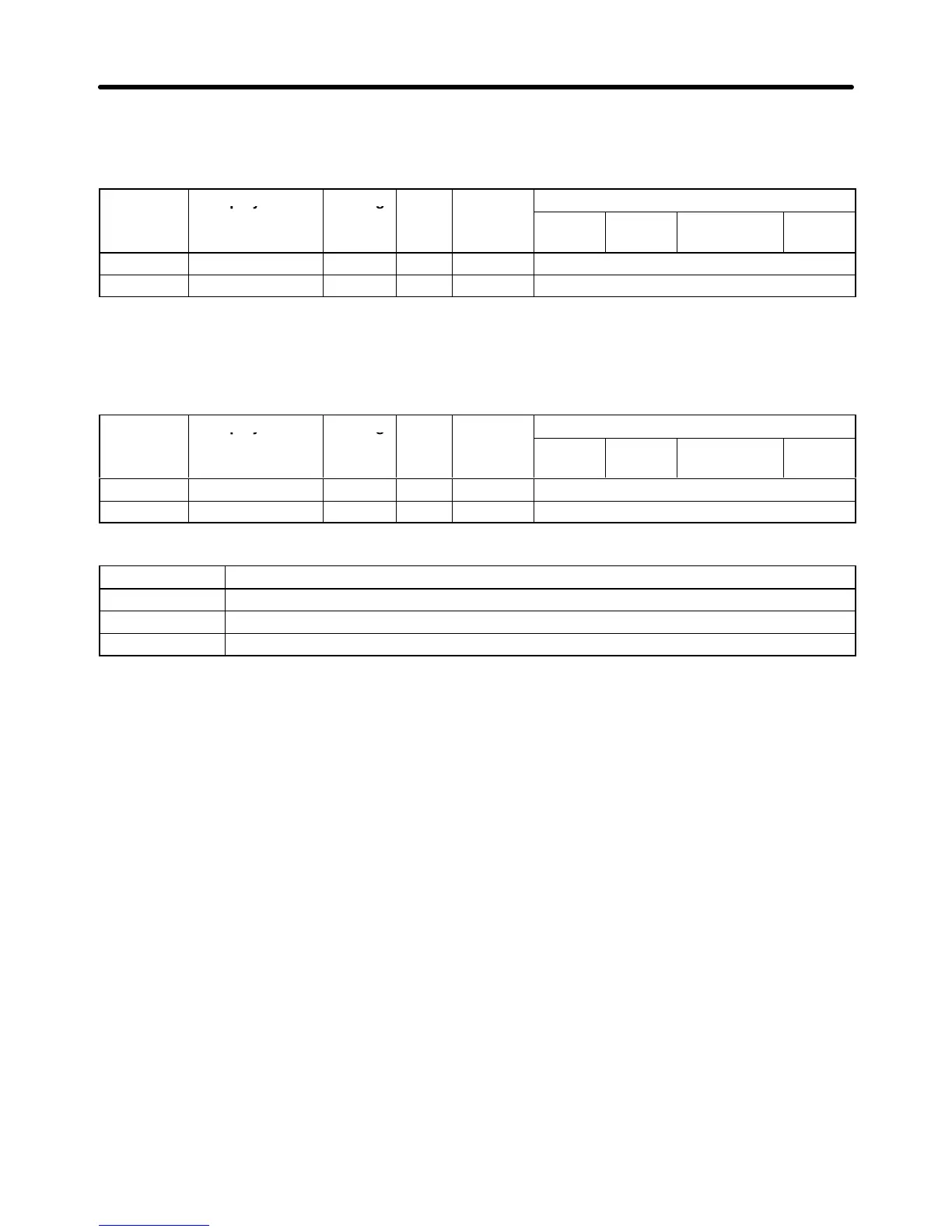
H3-05 Terminal 16 Sel 0 to 1F --- 1F Basic or Advanced
H3-09 Terminal 14 Sel 1 to 1F --- 1F Advanced
Note Set
either one of these parameters to torque reference (setting 13). (These parameters cannot be
changed during operation.)
• Next,
set the signal level
for the analog input terminal that was set to torque reference. These parame
-
ters cannot be changed during operation.
Parameter Display name Setting Units Default
Valid access levels
number
range setting
V/f
Control
V/f with
PG
Open Loop
Vector
Flux
Vector
H3-04 Term 16 Signal 0 or 1 --- 0 Basic or Advanced
H3-08 Term 14 Signal 0 to 2 --- 2 Advanced
Signal Level Settings
Setting Function
0 0- to +10-V input (When H3-08 is being set, be sure to disconnect jumper wire J1.)
1 0- to ±10-V input (When H3-08 is being set, be sure to disconnect jumper wire J1.)
2 4- to 20-mA input (H3-08 only)
Note 1. Set the proper signal level for the torque reference that you want to input.
Note 2. The
direction of the torque that is output is determined by the sign (polarity) of the signal that
was input. It is not determined by the direction of the run command (forward/reverse).
+Voltage (or current): Forward
torque reference (generally counter-clockwise; axis side)
–Voltage: Reverse torque reference (generally clockwise; axis side)
Since the polarity of the voltage input determines the direction, only forward torque refer-
ences
can be input when the “0 to +10 V” or “4 to 20 mA” signal level has been selected. If you
want to input reverse torque references, be sure to select the “0 to ±10 V” signal level.
Note 3. When
supplying a voltage input to the frequency reference current input (terminal 14), be sure
to
disconnect jumper
wire J1 on the control board. If the jumper wire isn’t disconnected, the
input resistor will be destroyed.
Advanced Operation Chapter
6