range setting
V/f
Control
V/f with
PG
Open Loop
Vector
Flux
Vector
b9-01 Zero Servo Gain 0 to 100 --- 5
Not applicable Advanced
b9-02 Zero Servo Count 0 to
16383
Pulses 10
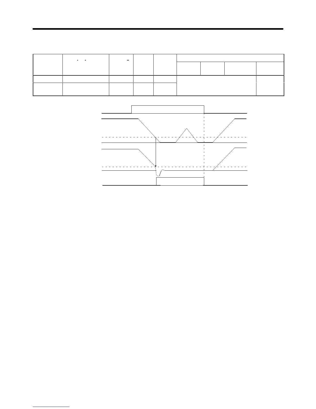
Zero-servo command
Frequency (speed) reference
Motor speed
Zero Servo End signal
Completely stopped by
zero-servo function
Excitation level (b2-01)
Excitation level (b2-01)
• Assign the zero-servo command (setting 72) to one of the multi-function inputs (H1-01 through
H1-06).
• The zero-servo status is entered when the frequency (speed) reference falls below the zero-speed
level (b2-01).
• Be sure to leave the run command input ON. If the run command is turned OFF, the output will be
interrupted and the zero-servo function will become ineffective.
• Adjust
the holding strength of the zero-servo position lock with parameter b9-01 (Zero Servo Gain).
Increasing
this setting
increases the holding strength, although vibration will occur if the setting is too
high. (Adjust the holding strength after adjusting the speed control (ASR) gain.)
• To
output the zero-servo status externally
, assign the Zero Servo End signal (setting 33) to one of the
multi-function
outputs (H2-01 through H2-03). The Zero Servo Count setting in b9-02 is enabled when
one of the multi-function outputs has been set to 33.
• The
“Zero Servo Count” specifies the
allowed of
fset from the starting position, and the Zero Servo End
signal
remains ON as long as the position is within this range (starting position
±
Zero Servo Count).
• Set
the Zero Servo Count to four times the number of pulses from the
PG (pulse generator or encoder),
as
shown in the following diagram. For example, when a 1,000 p/r encoder is being used, the number
of pulses would be 4,000 p/r after multiplying by four.
• The Zero Servo End signal will go OFF when the zero-servo command is turned OFF.
• These parameters cannot be changed during operation.
Note When
using the zero-servo function for an extended period
of time, limit the load to a maximum of
50%
of the Inverter
’
s rated output current. If a high holding strength is required of the zero-servo
Advanced Operation Chapter
6