5-9
Reference Source Settings
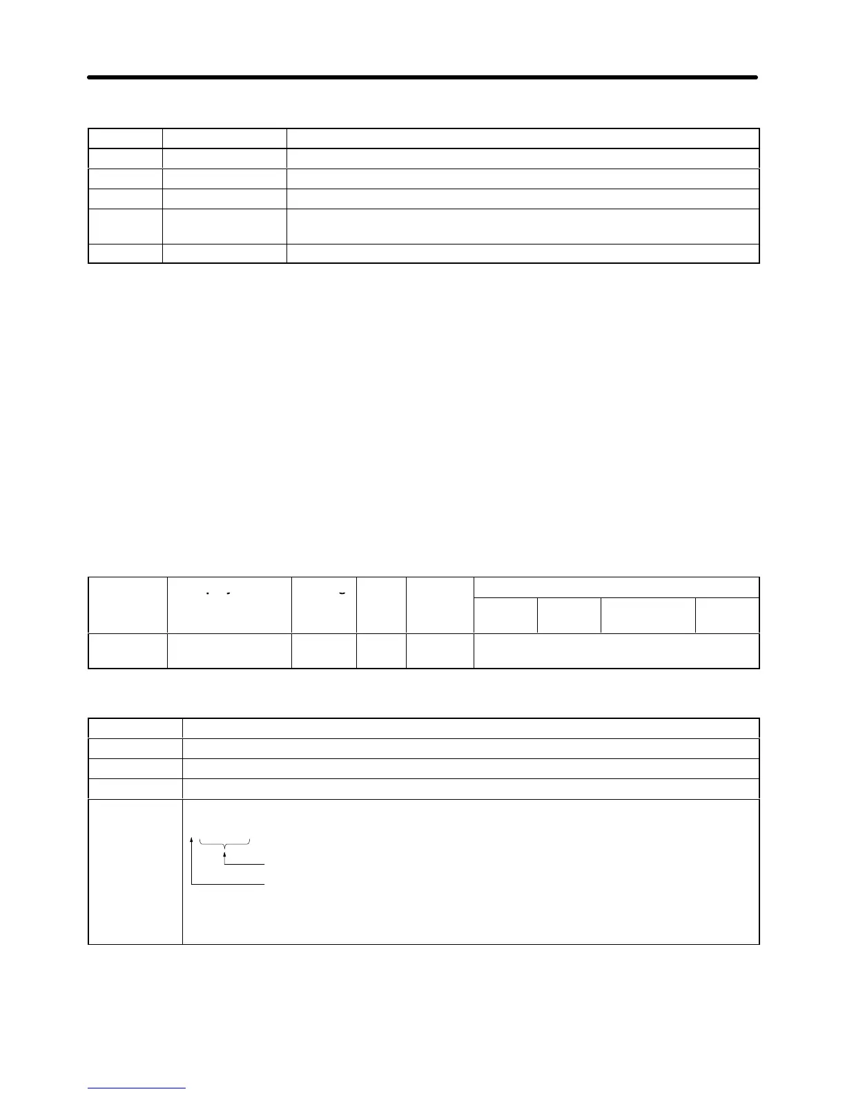
Setting Name Reference source
0 Operator Digital Operator
1 Terminals Control circuit terminals (analog inputs)
2 Serial Com Not used. (Do not set.)
3 Option PCB Optional
Card (CompoBus/D Communications
Card, SYSMAC BUS I/F Card,
Analog Command Card, or Digital Command Card)
4 EWS Not used. (Do not set.)
Note 1. The frequency reference is input from the Digital Operator, so set b1-01 to 0.
Note 2. The
source specified for the frequence reference is used as one of the frequency references
in
multistage control. If the frequence reference source is set to the Digital
Operator
, the fre
-
quence reference for d1-01 will be used and analog frequency reference (voltage/current)
input from the control terminal will be ignored. (The frequency for d1-01 will also be used if
operation is switched to local mode using the operation mode selection key.)
Note 3. Regardless
of the frequency source, the values set for frequency reference parameters 2 to 8
(d1-02 to d1-08) and the inching frequency reference parameter (d1-09) will be enabled.
H Setting the Frequency Reference Units (o1-03)
Parameter
o1-03 is used to set the units for setting and displaying the frequency reference; it cannot be
changed during operation.
Parameter Display name Setting Units Default
Valid access levels
number
range setting
V/f
Control
V/f with
PG
Open Loop
Vector
Flux
Vector
o1-03 Display Scaling 0 to
39,999
--- 0 Basic or Advanced
Display Unit Settings
Setting Function
0 0.01 Hz units
1 0.01 % units (The maximum frequency is 100%.)
2 to 39 r/min units (Set the number of poles)
40 to 39,999 Sets a particular value for the maximum frequency.
This number is the 4-digit setting without the decimal point.
This number indicates the location of the decimal point. (How many digits
there are after the decimal point.)
For example, set o1-03 to “12000” when you want to display “200.0” for the maximum
frequency.
Note When the 40 to 39,999 range is used, any scale can be set for the reference frequency.
For
example, the frequency reference can be set or displayed in units such as mm/s or m/min
to
coincide with a machine’s linear operating speed.
Basic Operation Chapter
5