5-30
Set whether phase A or phase B leads when the motor operates in the forward direction.
Parameter Display name Setting Units Default
Valid access levels*
number
range setting
V/f
Control
V/f with
PG
Open Loop
Vector
Flux
Vector
F1-05 PG Rotation Sel 0 or 1 --- 0 --- B --- B
Note B: Basic or Advanced
---: Not applicable.
PG Rotation Settings
Setting Function
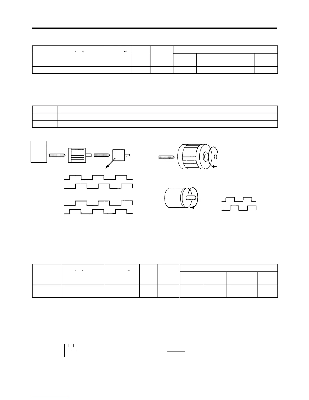
0 Phase A leads with forward command. (Phase B leads with reverse command.)
1 Phase B leads with forward command. (Phase A leads with reverse command.)
Inverter Motor PG (encoder)
[Setting: 0]
Phase A
Phase B
Pulse output
[Setting: 1]
Phase A
Phase B
Forward rotation in a typical motor:
Phase A leading in a typical PG:
Phase A
Phase B
The motor output axis
rotates in the counter-
clockwise direction with a
forward inverter command.
Phase A leads when the
input axis rotates clockwise.
H Setting the PG Pulse Output Monitor Division Ratio (F1-06)
This
parameter is ef
fective only when a 3G3FV
-PPB2 is used; it sets the division ratio used when the
pulse monitor output is connected to a pulse input device. This parameter cannot be changed during
operation.
Parameter Display name Setting Units Default
Valid access levels*
number
range setting
V/f
Control
V/f with
PG
Open Loop
Vector
Flux
Vector
F1-06 PG Output Ratio 001 to 032,
101 to 132
--- 1 --- B --- B
Note B: Basic or Advanced
---: Not applicable.
The
first digit in the setting (0 or 1) is n and the second two digits (01 to 32) are m. The division ratio is
calculated from n and m with the following equation:
Division ratio +
(1 ) n)
m
F1 - 06 =
m
n
The possible division ratio settings: 1/32 x F1-06x 1
Basic Operation Chapter
5