5-42
Parameter Setting Explanation
H4-01 Analog output selection (terminal 21) 21
Settings that allow multi-function analog output 1
to be used to monitor the ASR input.
H4-03 Analog output bias (terminal 21) 0.0
H4-04 Analog output selection (terminal 23) 5
Settings that allow multi-function analog output 2
to be used to monitor the motor speed.
H4-06 Analog output bias (terminal 23) 0.0
H4-07 Analog output level selection 1 This setting allows a 0 to ±10 V signal range to be
monitored.
The
multi-function analog outputs have the following functions with these parameter settings.
T
erminal
22
is the multi-function analog output common. (There are separate commons, terminals 27 and 37, for
the 3G3FV--CUE/CE.)
Multi-function analog output 1 (terminal 21): Outputs the Inverter’s ASR input (0 to ±10 V).
Multi-function analog output 2 (terminal 23): Outputs the actual motor speed (0 to ±10 V).
We recommend monitoring both the ASR input and the motor speed in order to observe a response
delay or deviation from the reference value, as shown in the following diagram.
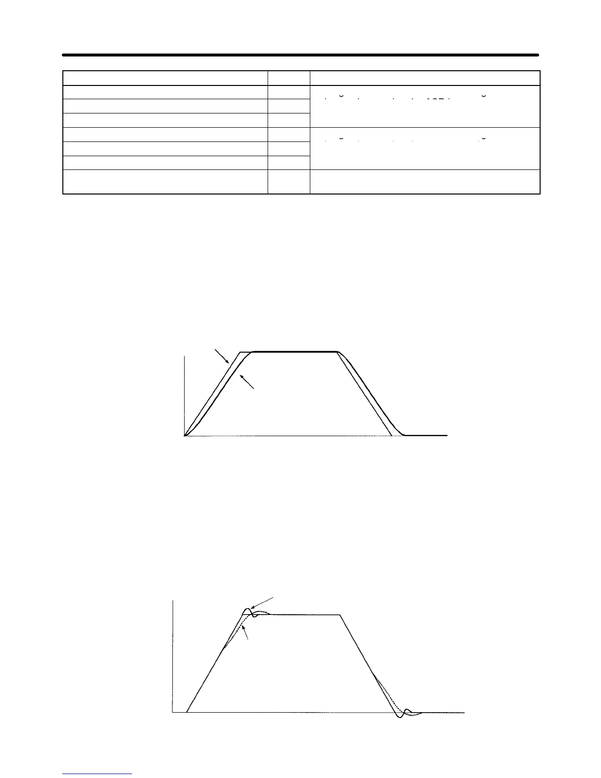
Example Waveforms
Motor speed
ASR input command
Motor speed (response)
Time
D Adjusting ASR Proportional Gain 1 (C5-01)
This gain setting adjusts the responsiveness of the speed control loop. The responsiveness is in-
creased
when this setting is increased. Usually this
setting is higher for larger loads. V
ibration will occur
if this setting is increased too much.
The following diagram shows changes that occur in the response when the ASR proportional gain is
changed.
Motor speed
The proportional gain is high.
(Vibration occurs when the gain is too high.)
Time
The proportional gain is low.
Basic Operation Chapter
5