5-40
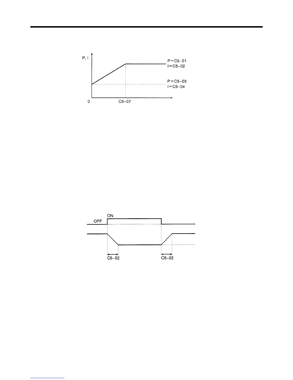
The following graph shows how the proportional gain and integral time approach ASR P Gain 2 and
ASR I Time 2 linearly as the frequency approaches zero.
Motor speed (Hz)
Note If
C5-07 is set to 0.0, ASR P Gain 1 and ASR I T
ime
1 are used for the proportional gain and inte
-
gral time at all frequencies.
H Multi-function Input Settings (H1-01 through H1-06)
D ASR Integral Reset (Setting E)
When
one of the multi-function inputs is set to “E,”
the input can be used to switch the speed control loop
between
P control and PI control. P control (integral reset) is used when the multi-function input is ON.
D ASR Proportional Gain Switch (Setting 77)
When
one of the multi-function inputs is set to “77,” the input can be used to switch between proportional
gain
1 and proportional gain 2. Proportional gain 2 (C5-03) is used when the multi-function input is ON.
This input has higher priority than the ASR switching frequency set in C5-07.
ASR Gain Switch signal
(a multi-function input)
Proportional gain (P)
Proportional gain determined
by motor speed.
C5-03 gain setting
Note The gain is changed linearly in integral time 1 (C5-02). The integral time setting isn’t switched.
Basic Operation Chapter
5