5-14
Settings
Only settings 0 and 1 can be used with Flux Vector control.
Setting Name Function
0 Ramp to Stop Deceleration stop
1 Coast to Stop Free-run stop
2 DC Injection to Stop DC
braking stop: Stops faster than free-run, without regenerative operation.
3 Coast w/Timer Free-run stop with timer: Run commands are ignored during deceleration
time.
The following diagrams show the operation of each stopping method. The “deceleration time” in the
diagrams refers to the selected deceleration time. (Deceleration times 1 through 4 are set with
C1-02, C1-04, C1-06, and C1-08.)
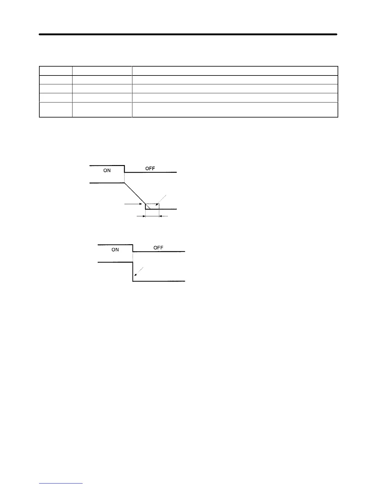
Deceleration Stop (b1-03 = 0)
Note 1. Decelerates
to a stop at a rate set with the
selected deceleration time.
Note 2. If the run command turns back ON during
deceleration, deceleration will be stopped
as
soon as the run command
turns ON and
the motor will be accelerated at the speci-
fied frequency.
DC braking
DC braking time at stop (b2-04)
Deceleration time
Excitation level (b2-01)
Output frequency
Run command
Free-run Stop (b1-03 = 1)
Note 1. After
the stop command is input, run commands are ignored until the minimum base
-
block time (L2-03) has elapsed.
Note 2. Do
not input the run command again until the motor has slowed down suf
ficiently
. If
the
run command turns ON, the motor will rapidly decelerate to a low frequency
, and
a main circuit overvoltage (OV) or overcurrent (OC) will be detected. If necessary,
use a timed free-run stop and set the deceleration time to a value large enough to
ensure sufficient deceleration (restarting is not possible during the deceleration
time).
Use one of
the multi-function inputs 1 to 6 (H1-01 to H1-06) for a speed search,
find the speed during the free-run stop, and ensure that acceleration is smooth.
The inverter output is shut OFF
when the stop command is input
and the run command goes OFF.
Output frequency
Run command
Basic Operation Chapter
5