6-9
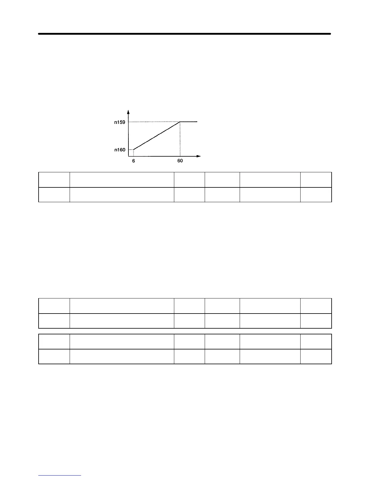
Set Values
• These parameters prevent the motor from over excitation due to voltage changes during energy-sav-
ing control.
• Set the upper limit of output voltage in percentage at each frequency based on the rated motor voltage
as 100%.
• Normally, the default settings do not need to be changed.
Output voltage
upper limit (%)
Output frequency (Hz)
n144
Probe Operation Voltage Limit Register 0190 Hex Changes during
operation
No
Setting
range
0 to 100 (%) Unit of
setting
1% Default setting 0
Set Values
• When the output frequency is constant for a certain period while the Inverter is in effective energy-sav-
ing control, the Inverter will be set to the primary level of energy-saving control by n140 (energy-saving
constant K2). Then the Inverter will be set to the secondary level (i.e., probe operation) for more effi-
cient, energy-saving control. Set the control voltage range of the Inverter in probe operation in param-
eter n144.
• Set the upper limit of probe operation voltage in percentage based on the rated motor voltage as
100%. Normally set the value to approximately 10%.
• No probe operation will be available if the value is set to 0.
n145
Probe Operation Control Voltage
Step at 100%
Register 0191 Hex Changes during
operation
No
Setting
range
0.1 to 10.0 (%) Unit of
setting
0.1% Default setting 0.5
n146
Probe Operation Control Voltage
Step at 5%
Register 0192 Hex Changes during
operation
No
Setting
range
0.1 to 10.0 (%) Unit of
setting
0.1% Default setting 0.2
Advanced Operation Chapter 6
 Loading...


