6-10
Set Values
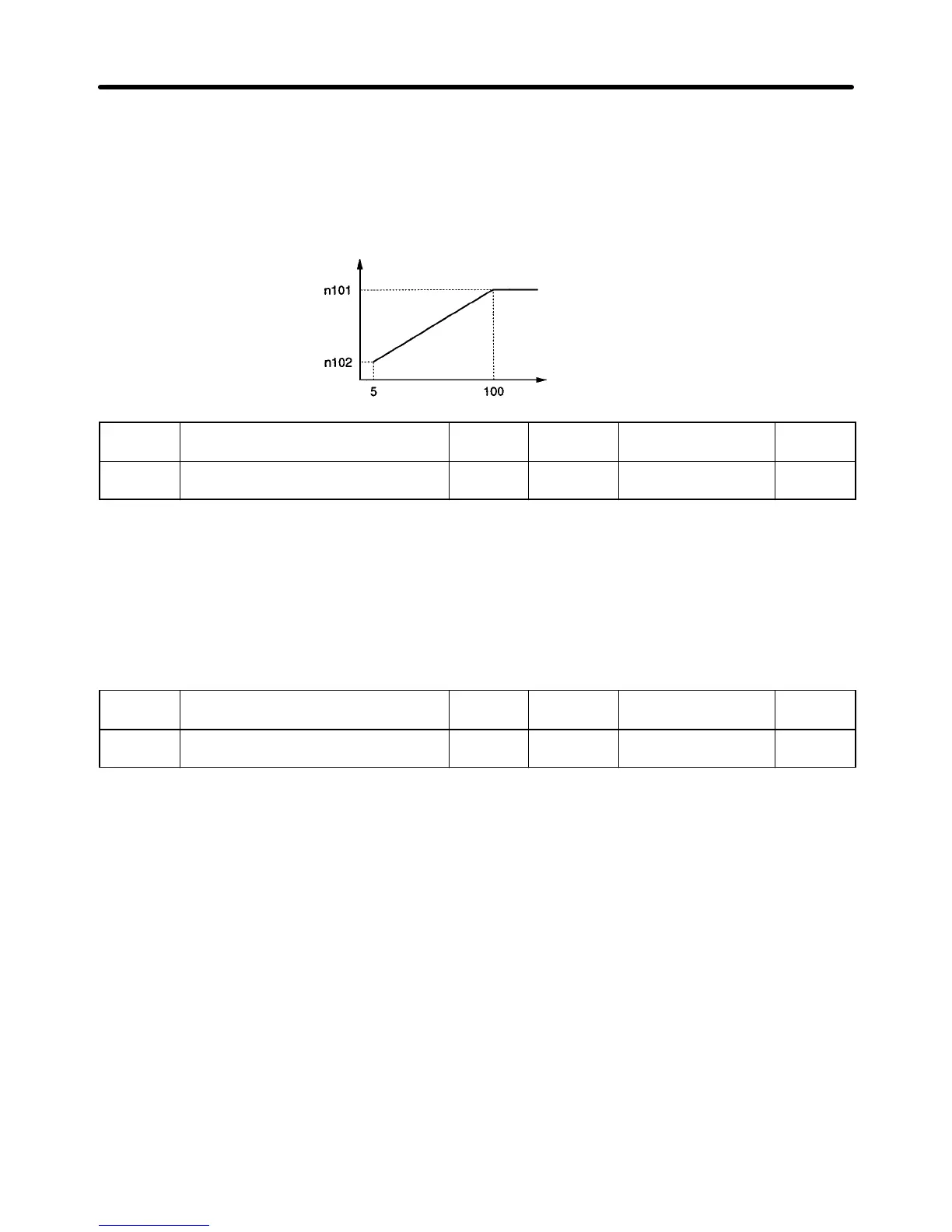
• Set the range of probe operation voltage in percentage based on the rated motor voltage as 100%.
• Normally, the default setting does not need to be changed.
• If the fluctuation of speed in probe operation is large, decrease the set value. If the response of the
Inverter in probe operation is slow, increase the set value.
Control voltage step (%)
Inverter output voltage (%)
n161
Power Detection Width for Probe
Operation Switching
Register 01A1 Hex Changes during
operation
No
Setting
range
0 to 100 (%) Unit of
setting
1% Default setting 10
Set Values
• Set this parameter to the detection width of power that sets the Inverter to probe operation. When the
fluctuation of power is within the detection width, the Inverter will be in probe operation.
• Set the width in percentage based on the power to be detected as 100%.
• Normally, the default setting does not need to be changed.
• The Inverter will operate with a power detection width of 10% if the value is set to 0.
n162
Power Detection Filter Constant Register 01A2 Hex Changes during
operation
No
Setting
range
0 to 255 Unit of
setting
1 (4 ms) Default setting 5
Set Values
• Set this parameter to the filter time constant of the power detection block of the Inverter operating in
probe operation.
Filter time constant (ms) = Set value in n162 x 4 (ms)
• Normally, the default setting does not need to be changed.
• The Inverter will operate with a time constant of 20 ms if the value is set to 0.
Advanced Operation Chapter 6
 Loading...


