7-39
put) of the Inverter, and monitors the Inverter status.
Three Inverters with Slave addresses from 01 to 03 are installed for communications.
D Checking the Register Numbers
• In the above example, the following three registers are required.
Control Input: Register 0001 Hex for RUN command
Frequency Reference: Register 0002 Hex
Control Output: Register 002C Hex for Inverter status
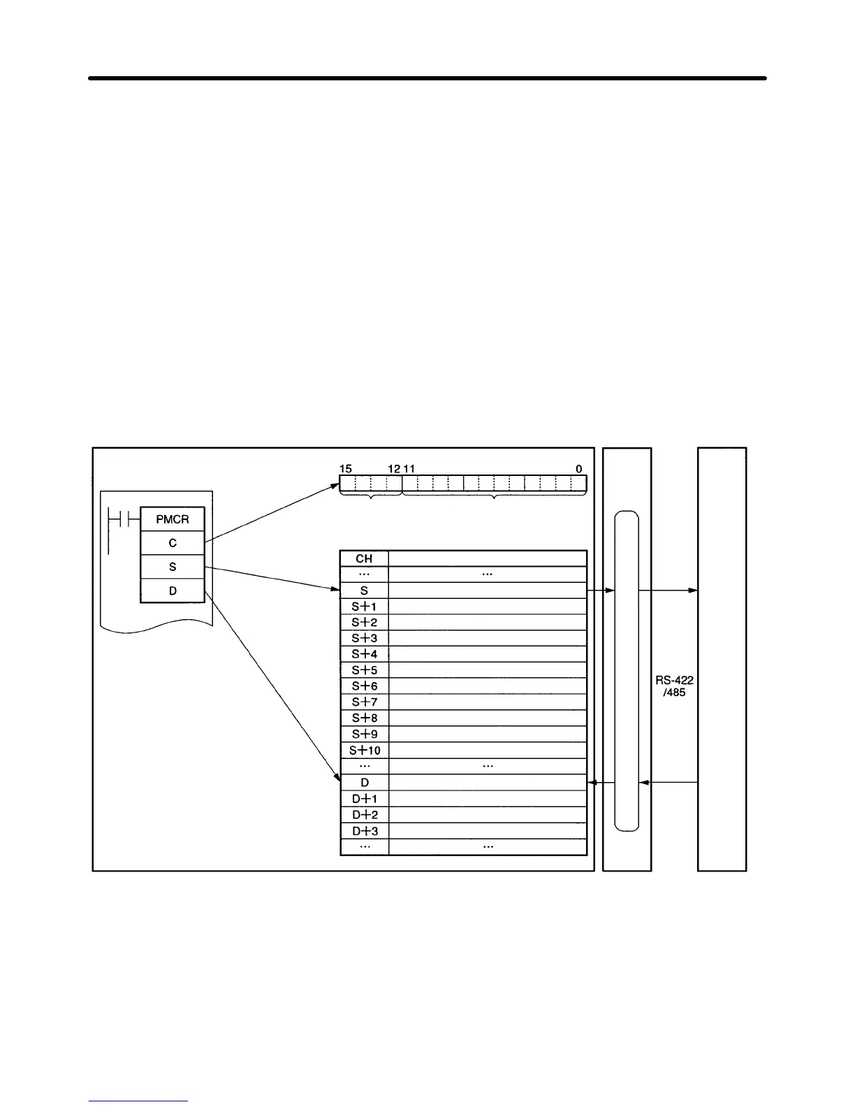
D Memory Allocations
• The PMCR instruction sends each Slave the data in consecutive words specified by the operand and
beginning with the first word (S), and writes in the memory area beginning with the first word (D) the
data received.
• The following memory allocations are made in the above example.
SYSMAC CS/CJ-series or C200HX/HG/HE
Programmable Controllers
Communications
Board
3G3MV
C: Control data (See note.)
Communica-
tions port
1: Port A
2: Port B
Sequence No.
000 to 999 (BCD)
Data
No. of data items send in accordance with PMCR
instruction (000B)
No. of Slaves (0003)
First Slave address (0001)
RUN command to Slave 1
Frequency reference to Slave 1
Second Slave address (0002)
RUN command to Slave 2
Frequency reference to Slave 2
Third Slave address (0003)
RUN command to Slave 3
Frequency reference to Slave 3
No. of data items received in accordance with
PMCR instruction (0004)
Slave 1 Inverter status
Slave 2 Inverter status
Slave 3 Inverter status
Note Control data on the SYSMAC
C200HX/HG/HE is indicated. The
SYSMAC CS/CJ Series uses dif-
ferent control data.
Protocol macro function
H Creating a New Project and Protocol
1. Select New from the File in the Menu Bar or click on the New icon with the left button of the mouse to
create a new project.
2. If CX-Protocol is used, set the PLC name, PLC model, and network type according to the actual
conditions.
Communications Chapter 7

 Loading...


