10-7
Param-
eter
No.
Ref-
er-
ence
page
Changes
during
opera-
tion
Default
setting
Unit
of
set-
ting
Set-
ting
range
DescriptionNameRegis-
ter No.
(Hex)
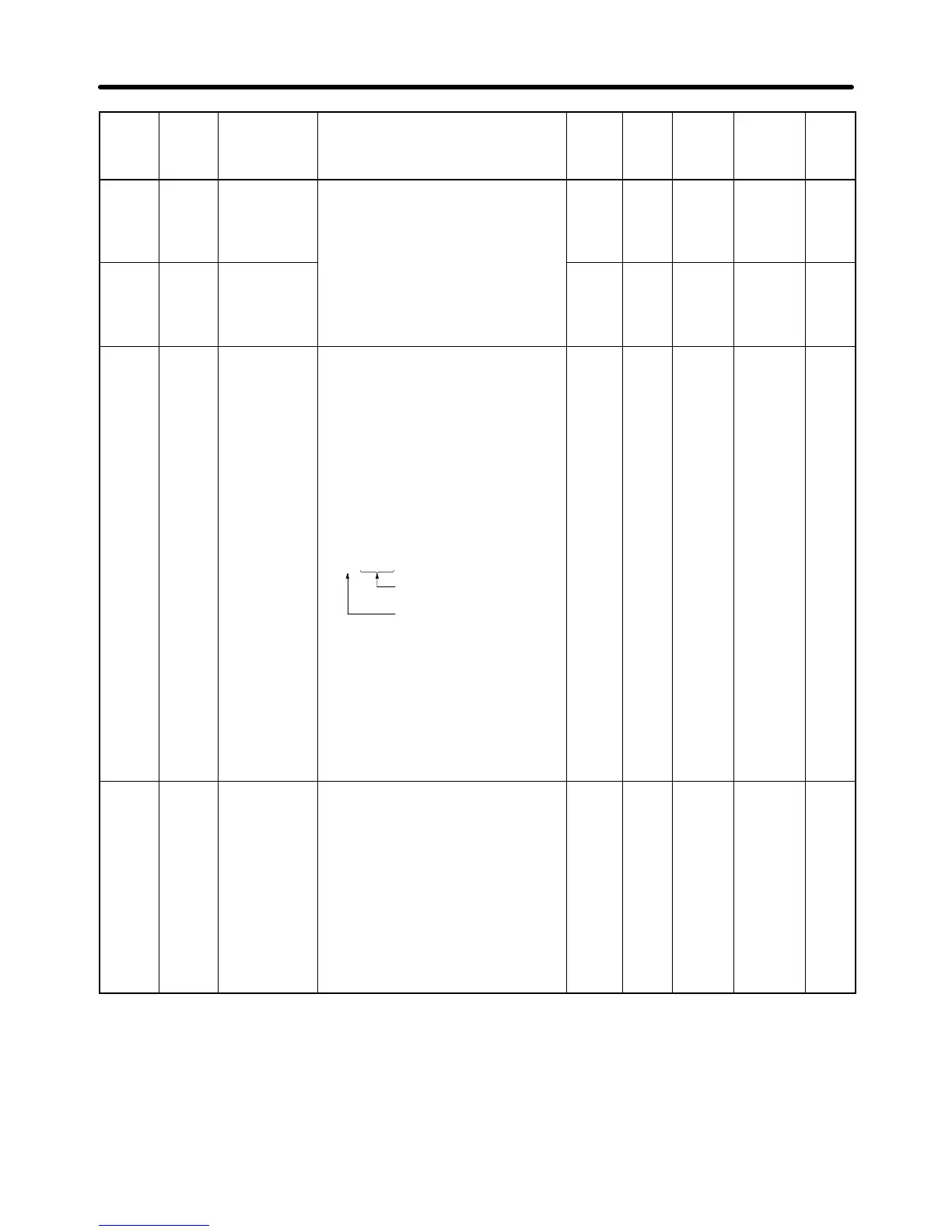
n033 0121 Upper fre-
quency refer-
ence limit
Used to set the upper and lower fre-
quency reference limits in percentage
based on the maximum frequency as
100%.
*
If n034 is set to a value less than
0 to
110
1% 100 No 5-12
n034 0122 Lower fre-
quency refer-
ence limit
If n034 is set to a value less than
the minimum output frequency
(n016), the Inverter will have no
output when a frequency reference
less than the minimum output fre-
quency input is input.
0 to
110
1% 0 No 5-12
n035 0123 Frequency
reference set-
ting/display
unit selection
Set the unit of frequency reference
and frequency-related values to be
set or monitored through the Digital
Operator.
0: 0.01 Hz
1: 0.1%
2 to 39: rpm (number of motor poles)
40 to 3,999: The value to be set or
monitored at max. frequency.
Set the value as shown below.
* To display 50.0, for example, set
the value to 1500. The setting unit
of each parameter or monitor item
below varies with the decimal
place.
• Parameters: n024 through n032 and
n120 through n127
• Monitor Items: U-01 and U-02
jjjj
Three digits
Decimal place (See
note below)
0 to
3,999
1 0 No 5-18
n036 0124 Rated motor
current
Used to set the rated motor current
for motor overload detection (OL1)
based on the rated motor current.
* In vector control mode, this param-
eter is used as a constant for vec-
tor control operation.
* Motor overload detection (OL1) is
disabled by setting the parameter
to 0.0.
* The rated motor current is default
to the standard rated current of the
maximum applicable motor.
0.0 to
150%
of rated
output
current
of the
Inverter
0.1 A Varies
with the
capac-
ity
No 5-5
5-7
List of Parameters Chapter 10

 Loading...


