2-16
Symbol SpecificationName
Out-
put
MA Multi-function contact out-
put (Normally open: Fault)
Relay output
1 A max. at 30 V DC
MB Multi-function contact out-
put (Normally closed:
Fault)
1 A max. at 250 V AC
MC Multi-function contact out-
put common
P1 Multi-function photocoupler
output 1 (During opera-
tion
)
Open collector output 50 mA max.
at 48 V DC
P2 Multi-function photocoupler
output 2 (Frequency
matching
)
PC Multi-function photocoupler
output common
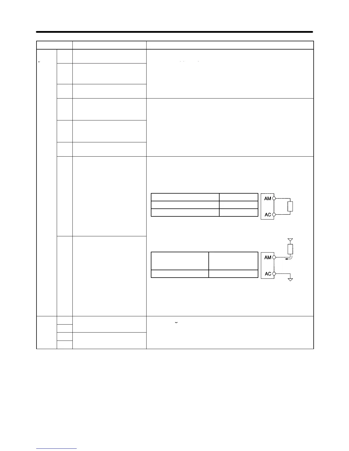
AM Multi-function analog out-
put
• Analog output: 2 mA max. at 0 to 10 V DC
• Pulse train output (max. output voltage: 12 V DC)
(See note 4.)
When Used as Voltage Output
Load impedance
1.5 kΩ min.
10 kΩ min.
Output voltage (insulation type)
+5 V
+10 V
Load
imped-
ance
External
AC Multi-function analog out-
put common
When External Power Supply is Used
Note Do not use a 5-V DC or 24-V DC external power sup-
ply. Doing so can cause internal circuit damage or
malfunctioning.
Input current (mA)
from external power
supply
16 mA max.
External power supply (V)
12 V DC (±5%)
power
supply
12 V DC
Load
imped-
ance
Input
current
16 mA
max.
External power
supply ground
Com-
R+
Receiver side Conforming to RS-422/485
mu-
R–
n
ca-
S+
Sender side
S–
Note 1. Parameter settings can be used to select various functions for multi-function inputs 1 to 7,
multi-function contact outputs, and multi-function photocoupler outputs. The functions in
parentheses are the default settings.
Note 2. NPN is the default setting for these terminals. Wire them by providing a common ground. No
external power supply is required.
Note 3. To provide an external power supply and wire the terminals through a common positive line,
set SW1 to PNP and use a 24 V DC ±10% power supply.
Design Chapter 2

 Loading...


