EasyManuals Logo

Omron SYSDRIVE 3G3MV SERIES User Manual

Omron SYSDRIVE 3G3MV SERIES
344 pages
To Next Page IconTo Next Page
To Previous Page IconTo Previous Page
Page #49 background imageLoading...
Page #49 background image
2-17
Note 4. When multi-function analog outputs are used for pulse train outputs, they can be directly con-
nected to the pulse train inputs at other 3G3MV-series Inverters for simple synchronization or
other applications.
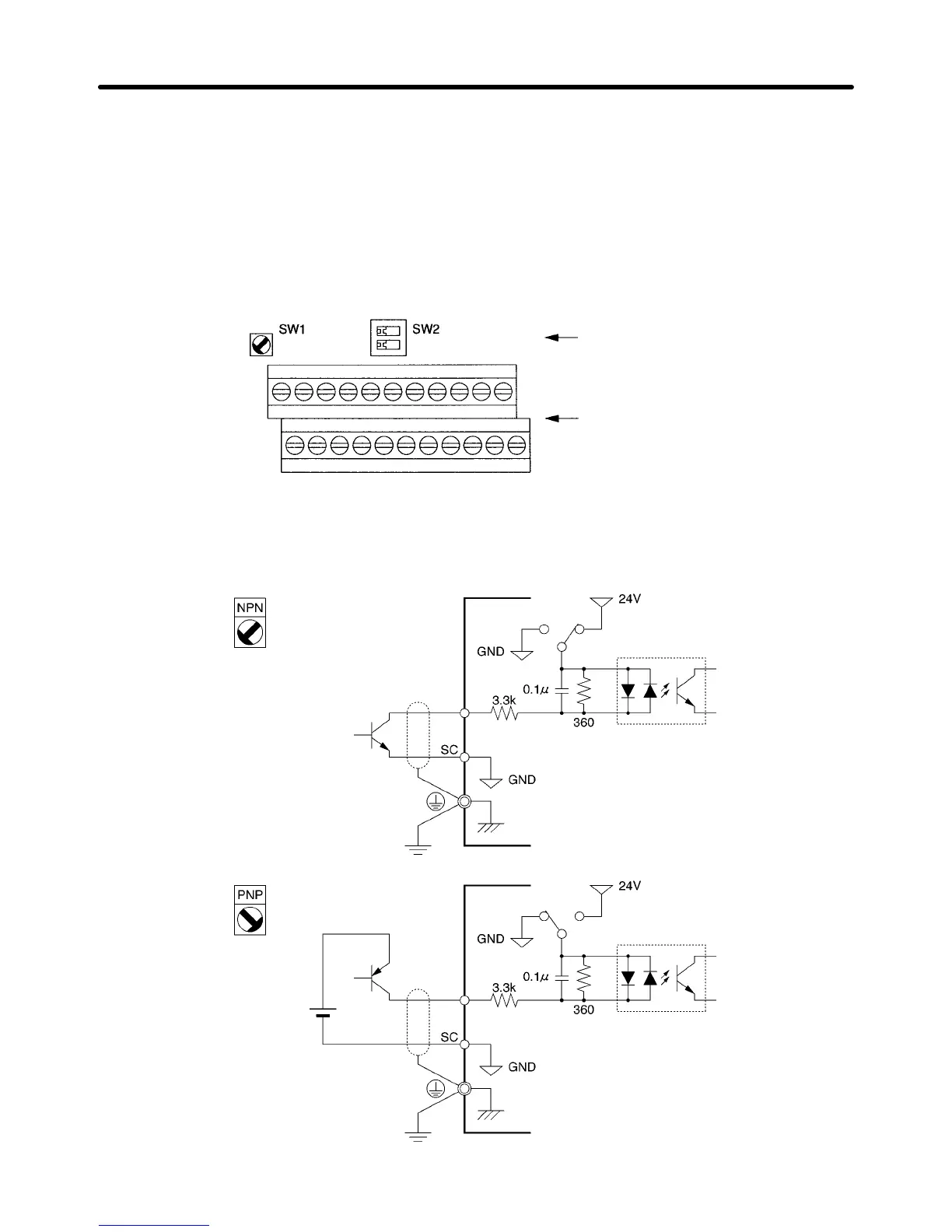
H Selecting Input Method
Switches SW1 and SW2, both of which are located above the control circuit terminals, are used for
input method selection.
Remove the front cover and optional cover to use these switches.
Selector
Control circuit
terminal block
D Selecting Sequence Input Method
By using SW1, NPN or PNP input can be selected as shown below.
24 V DC
(±10%)
S1 to 7
S1 to 7
(Default setting)
SW1
SW1
Design Chapter 2

Table of Contents

Questions and Answers:

Question and Answer IconNeed help?

Do you have a question about the Omron SYSDRIVE 3G3MV SERIES and is the answer not in the manual?

Omron SYSDRIVE 3G3MV SERIES Specifications

General IconGeneral
ModelSYSDRIVE 3G3MV SERIES
CategoryInverter
Input Frequency50/60 Hz
Output Frequency0.1 to 400 Hz
Cooling MethodForced Air Cooling
Input Voltage200 to 240 VAC, 380 to 480 VAC
Horsepower Range0.1 to 15 HP
Power Range0.1 to 11 kW
Overload Capacity150% for 60 seconds
Braking UnitBuilt-in
Protection FunctionsOvercurrent, Overvoltage, Undervoltage, Overheat
CommunicationRS-485
Ambient Temperature-10 to 50°C
Storage Temperature-20 to 65°C
Humidity5 to 95% RH (non-condensing)
Vibration5.9 m/s² or less
Voltage Class200V, 400V

Related product manuals