2-26
D Installing a Noise Filter on the Power Supply Side
The Inverter’s outputs utilize high-speed switching, so noise may be transmitted from the Inverter to the
power line and adversely affect other devices in the vicinity. It is recommended that a Noise Filter be
installed at the Power Supply to minimize this noise transmission. Conversely, noise can also be re-
duced from the power line to the Inverter.
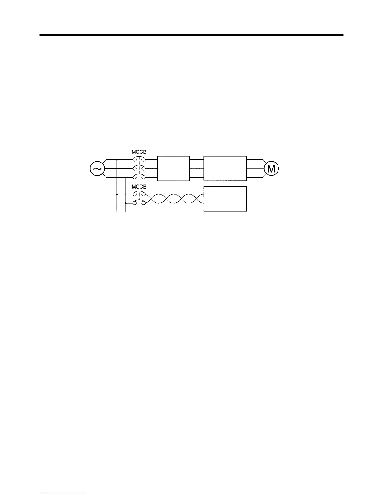
Wiring Example 1
Power
supply
3G3MV
SYSDRIVE
SYSMAC or
other control
device
Noise
Filter
Input Noise Filters
Simple Input Noise Filter: 3G3EV-PLNFDj
Input Noise Filter: 3G3IV-PFNj
EMC-conforming Input Noise Filter: 3G3MV-PRSj
Note Use a noise filter designed for Inverters. A general-purpose noise filter will be less effective and
may not reduce noise.
H Wiring on the Output Side of the Main Circuit
D Connecting the Terminal Block to the Load
Connect output terminals U/T1, V/T2, and W/T3 to motor lead wires U/T1, V/T2, and W/T3.
Check that the motor rotates forward with the forward command. Switch over any two of the output ter-
minals to each other and reconnect if the motor rotates in reverse with the forward command.
D Never Connect a Power Supply to Output Terminals
Never connect a power supply to output terminals U/T1, V/T2, or W/T3.
If voltage is applied to the output terminals, the internal circuit of the Inverter will be damaged.
D Never Short or Ground Output Terminals
If the output terminals are touched with bare hands or the output wires come into contact with the
Inverter casing, an electric shock or grounding will occur. This is extremely hazardous.
Also, be careful not to short the output wires.
D Do not Use a Phase Advancing Capacitor or Noise Filter
Never connect a phase advance capacitor or LC/RC Noise Filter to the output circuit.
Doing so will result in damage to the Inverter or cause other parts to burn.
D Do not Use an Electromagnetic Switch of Magnetic Contactor
Do not connect an electromagnetic switch of magnetic contactor to the output circuit.
If a load is connected to the Inverter during running, an inrush current will actuate the overcurrent pro-
tective circuit in the Inverter.
Design Chapter 2

 Loading...


