2-28
D Countermeasures against Radio Interference
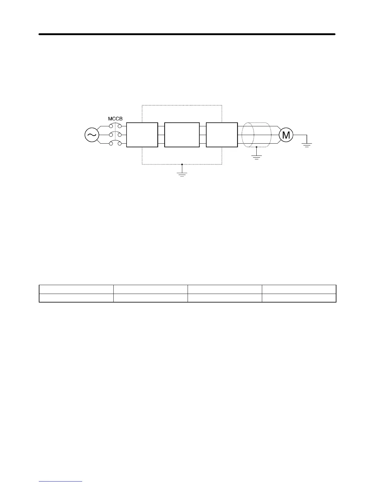
Radio noise is generated from the Inverter as well as the input and output lines. To reduce radio noise,
install Noise Filters on both input and output sides, and also install the Inverter in a totally enclosed steel
box.
The cable between the Inverter and the motor should be as short as possible.
Power supply
Noise
Filter
Steel box
3G3MV
SYSDRIVE
Metal pipe
Noise
Filter
D Cable Length between Inverter and Motor
As the cable length between the Inverter and the motor is increased, the floating capacity between the
Inverter outputs and the ground is increased proportionally. The increase in floating capacity at the In-
verter outputs causes the high-frequency leakage current to increase, and this may adversely affect
peripheral devices and the current detector in the Inverter’s output section. To prevent this from occur-
ring, use a cable of no more than 100 meters between the Inverter and the motor. If the cable must be
longer than 100 meters, take measures to reduce the floating capacity by not wiring in metallic ducts, by
using a separate cable for each phase, and so on.
Also adjust the carrier frequency (set in n80) according to the cable length between the Inverter and the
motor, as shown in the table below.
Cable length 50 m or less 100 m or less More than 100 m
Carrier frequency 10 kHz max. 5 kHz max. 2.5 kHz max.
D Single-phase Motors Cannot Be Used
The Inverter is not suited for the variable speed control of single-phase motors.
Single-phase motors are either capacitor start motors or split-phase start motors. (The method for de-
termining rotation direction at startup is different.) If a capacitor start motor is used, the capacitor may be
damaged by a sudden electric discharge caused by Inverter output. If a split-phase start motor is used,
the starting coil may burn because the centrifugal switch does not operate.
Design Chapter 2

 Loading...


