2-38
H Conforming to EC Directives
D Wiring the Power Supply
Make sure that the Inverter and Noise Filter are grounded together.
• Always connect the power input terminals (R/L1, S/L2, and T/L3) and power supply via a dedicated
Noise Filter.
• Reduce the length of the ground wire as much as possible.
• Locate the Noise Filter as close as possible to the Inverter. Make sure that the cable length between
the Noise Filter and the Inverter does not exceed 40 cm.
• The following Noise Filters are available.
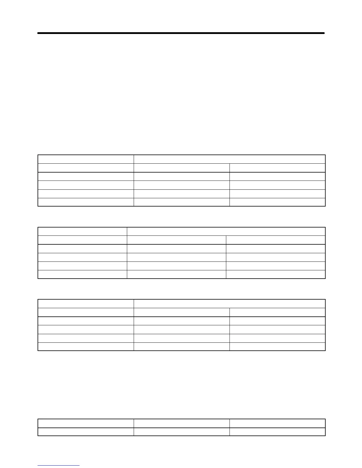
3-phase 200-V AC Noise Filter
Inverter 3-phase 200-V AC Noise Filter (Rasmi Electronics Ltd.)
Model 3G3MV- Model 3G3MV- Rated current (A)
A2001/A2002/A2004/A2007 PRS2010V 10
A2015/A2022 PRS2020V 16
A2037 PRS2030V 26
A2055/A2075 PRS2030V 50
Single-phase 200-V AC Noise Filter
Inverter Single-phase 200-V Noise Filter (Rasmi Electronics Ltd.)
Model 3G3MV- Model 3G3MV- Rated current (A)
AB001/AB002/AB004 PRS1010V 10
AB007/AB015 PRS1020V 20
AB022 PRS1030V 30
AB037 PRS1040V 40
3-phase 400-V AC Noise Filter
Inverter 3-phase 400-V AC Noise Filter (Rasmi Electronics Ltd.)
Model 3G3MV- Model 3G3MV- Rated current (A)
A4002/A4004 PRS3005V 5
A4007/A4015/A4022 PRS3010V 10
A4037 PRS3020V 15
A4055/A4075 PRS3030V 30
D Connecting a Motor to the Inverter
• When connecting a motor to the Inverter, be sure to use a cable with a braided shield.
• Reduce the length of the cable as short as possible and ground the shield on the Inverter side as well
as the motor side. Make sure that the cable length between the Inverter and the motor does not exceed
20 cm. Furthermore, it is recommended that a clamp core (Clamp Filter) be connected close to the
output terminals of the Inverter.
Product Model Manufacturer
Clamp Filter ZCAT3035-1330 TDK
Design Chapter 2

 Loading...


