3-6
D Status Monitor
Item Display Display
unit
Function
U-01 Frequency reference Hz (see
note 1)
Monitors the frequency reference. (Same as FREF)
U-02 Output frequency Hz (see
note 1)
Monitors the output frequency. (Same as FOUT)
U-03 Output current A Monitors the output current. (Same as IOUT)
U-04 Output voltage V Monitors the internal output voltage reference value of the
Inverter.
U-05 DC bus voltage V Monitors the DC voltage of the internal main circuit of the
Inverter.
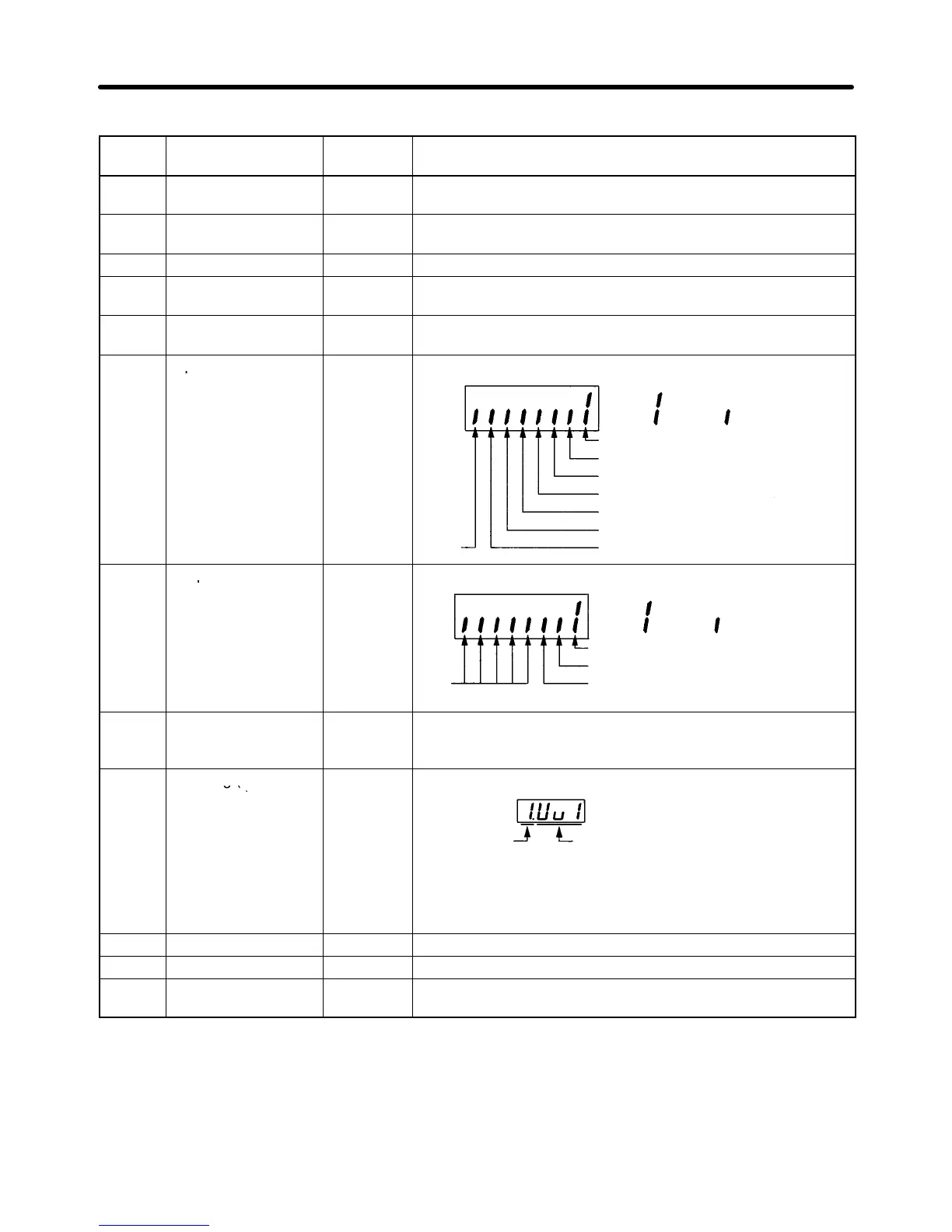
U-06 Input terminal status ---
Shows the ON/OFF status of inputs.
: ON : OFF
Not
used
Terminal S1: Multi-function input 1
Terminal S2: Multi-function input 2
Terminal S3: Multi-function input 3
Terminal S4: Multi-function input 4
Terminal S5: Multi-function input 5
Terminal S6: Multi-function input 6
Terminal S7: Multi-function input 7
U-07 Output terminal ---
Shows the ON/OFF status of outputs.
status
: ON : OFF
Not
used
Terminal MA: Multi-function contact output
Terminal P1: Multi-function photo-coupler
output 1
Terminal P2: Multi-function photo-coupler
output 2
U-08 Torque monitor % Displays the torque being currently output as a percentage of
the rated motor torque. This display can only be made in
vector control mode.
U-09 Error log (most
---
The four most recent errors can be checked.
recent one)
Error
Error
generation
item
Note “1” means that the latest error is displayed. Press the
Increment Key to display the second latest error. A maxi-
mum of four errors can be displayed.
U-10 Software No. --- OMRON use only.
U-11 Output power W Monitors the output power of the Inverter. (See note 2.)
U-13 Accumulated
operating time
x10H Monitor the accumulated operating time in 10-second units.
(See note 3.)
Preparing for Operation and Monitoring Chapter 3

 Loading...


