3-7
Item FunctionDisplay
unit
Display
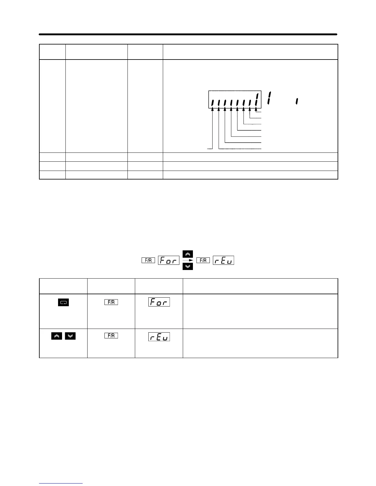
U-15 Communications
error
--- Displays communications errors that occur during serial
communications (RS-422/RS-485). The errors that are
displayed have the same content as the serial
communications error at register number 003D Hex.
: Error
CRC error
: Normal
operation
Data length error
(Not used.)
Parity error
Overrun error
Communications time-over
(Not used.)
Framing error
U-16 PID feedback % Monitors the PID control feedback (Max. frequency: 100%)
U-17 PID input % Monitors the PID control input (Max. frequency: 100%)
U-18 PID output % Monitors the PID output (Max. frequency: 100%)
Note 1. The setting unit of the frequency reference and output frequency is determined by the set
value in n035. The default unit is Hz.
Note 2. The output power monitor is not displayed in vector control mode. “––––” is displayed instead.
Note 3. This function is provided for 200- and 400-V (5.5-/7.5-kW) Inverters only.
H Example of Forward/Reverse Selection Settings
Key sequence Indicator Display
example
Explanation
Press the Mode Key repeatedly until the F/R indicator
is lit.
The present setting will be displayed.
For: Forward; rEv: Reverse
Use the Increment or Decrement Key to change the
direction of motor rotation. The direction of motor
rotation selected will be enabled when the display
changes after the key is pressed.
Note The direction of motor rotation can be changed, even during operation.
Preparing for Operation and Monitoring Chapter 3

 Loading...


