LED Operator Display Fault Name
or
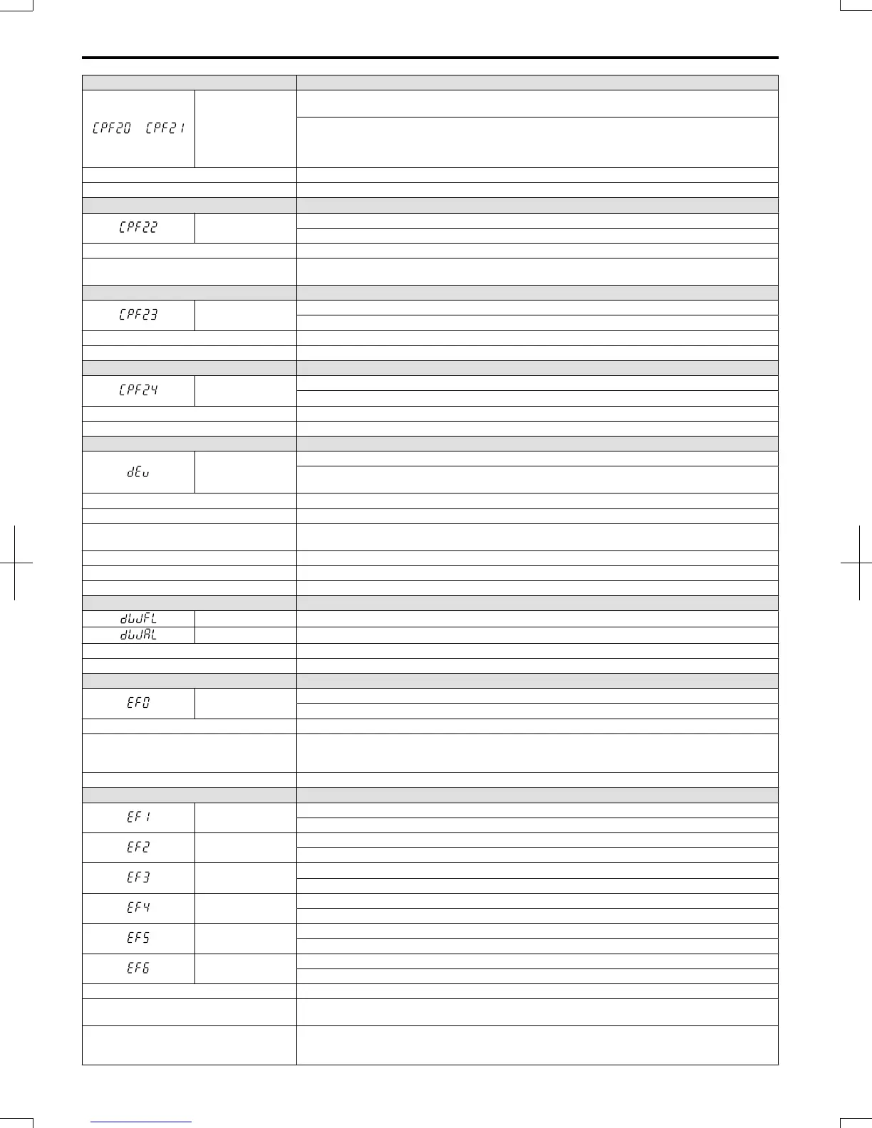
CPF20 or CPF21
One of the following faults occurred: RAM fault, FLASH memory error, watchdog circuit exception,
clock error
• RAM fault.
• FLASH memory error (ROM error).
• Watchdog circuit exception (self-diagnostic error).
• Clock error.
Cause Possible Solution
Hardware is damaged. Replace the drive.
LED Operator Display Fault Name
CPF22
A/D Conversion Fault
A/D conversion error.
Cause Possible Solution
Control circuit is damaged.
• Cycle power to the drive. Refer to Diagnosing and Resetting Faults on page 252.
• If the problem continues, replace the drive.
LED Operator Display Fault Name
CPF23
PWM Feedback Fault
PWM feedback error.
Cause Possible Solution
Hardware is damaged. Replace the drive.
LED Operator Display Fault Name
CPF24
Drive Capacity Signal Fault
Entered a capacity that does not exist. (Checked when the drive is powered up.)
Cause Possible Solution
Hardware is damaged. Replace the drive.
LED Operator Display Fault Name
dEv
Speed Deviation (for Simple V/f with PG)
According to the pulse input (RP), the speed deviation is greater than the setting in F1-10 for longer
than the time set to F1-11.
Cause Possible Solution
Load is too heavy. Reduce the load.
Acceleration and deceleration times are set
too short.
Increase the acceleration and deceleration times (C1-01 through C1-08).
The load is locked up. Check the machine.
Parameters are not set appropriately. Check the settings of parameters F1-10 and F1-11.
Motor brake engaged. Ensure the motor brake releases properly.
LED Operator Display Fault Name
dWFL FBDs Fault
dWAL FBDs Program Error Output
Cause Possible Solution
Fault output by FBDs program • Correct whatever caused the fault.
LED Operator Display Fault Name
EF0
Option Card External Fault
An external fault condition is present.
Cause Possible Solution
An external fault was received from the PLC
with other than F6-03 = 3 “alarm only” (the
drive continued to run after external fault).
• Remove the cause of the external fault.
• Remove the external fault input from the PLC.
Problem with the PLC program. Check the PLC program and correct problems.
LED Operator Display Fault Name
EF1
External Fault (input terminal S1)
External fault at multi-function input terminal S1.
EF2
External Fault (input terminal S2)
External fault at multi-function input terminal S2.
EF3
External Fault (input terminal S3)
External fault at multi-function input terminal S3.
EF4
External Fault (input terminal S4)
External fault at multi-function input terminal S4.
EF5
External Fault (input terminal S5)
External fault at multi-function input terminal S5.
EF6
External Fault (input terminal S6)
External fault at multi-function input terminal S6.
Cause Possible Solution
An external device has tripped an alarm
function.
Remove the cause of the external fault and reset the fault.
Wiring is incorrect.
• Ensure the signal lines have been connected properly to the terminals assigned for external fault
detection (H1- = 20 to 2F).
• Reconnect the signal line.
6.4 Fault Detection
232
SIEP C710606 20 OYMC AC Drive - V1000 User Manual
7/16/2008-13:23