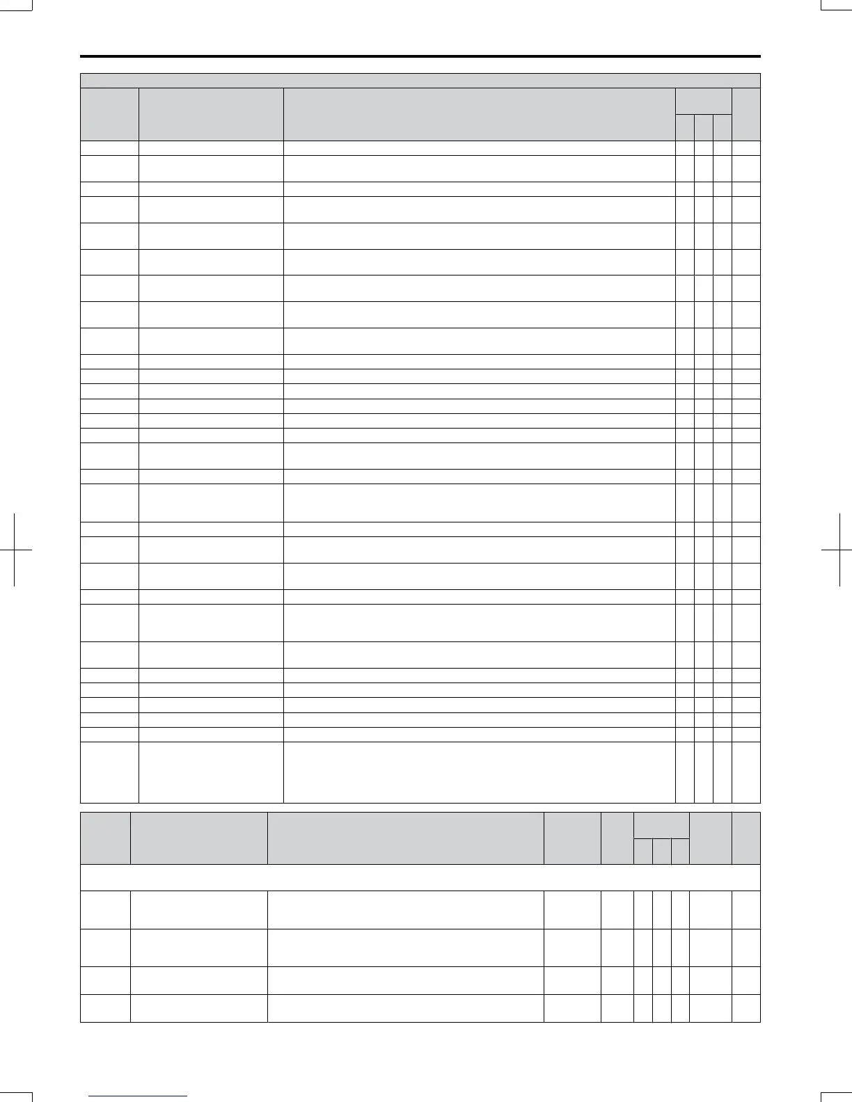
H2 Multi-Function Digital Output Settings
H2-
Setting
Function Description
Control
Mode
Pg.
V/f
O
LV
P
M
11 Reset Command Active Closed: Reset command to the drive is active. O O O 173
12 Timer Output
Timer output, controlled by b4-01 and b4-02. Used in conjunction with the digital
input (H1- = 18 “timer function”).
O O O 173
13 Speed Agree 2 Closed: When drive output frequency equals the frequency reference +/- L4-04. O O O 173
14 User Set Speed Agree 2
Closed: When the drive output frequency is equal to the value in L4-03 (plus or minus
L4-04).
O O O 174
15 Frequency Detection 3
Closed: When the drive output frequency is less than or equal to the value in L4-03
with the hysteresis determined by L4-04.
O O O 174
16 Frequency Detection 4
Closed: When the output frequency is greater than or equal to the value in L4-03 with
the hysteresis determined by L4-04.
O O O 175
17 Torque Detection 1 (N.C.)
Open: When the output current/torque exceeds the value set in parameter L6-02 for
more time than is set in parameter L6-03.
O O O 173
18 Torque Detection 2 (N.O.)
Closed: When the output current/torque exceeds the value set in parameter L6-05 for
more time than is set in parameter L6-06.
O O O 173
19 Torque Detection 2 (N.C.)
Open: Output current/torque exceeds the value set in parameter L6-05 for more time
than is set in parameter L6-06.
O O O 173
1A Reverse Direction Closed: Drive is running in the reverse direction. O O O 175
1B During Baseblock (N.C.) Open: Drive is in Baseblock condition. Output is disabled. O O O 176
1C Motor 2 Selection
Closed: Motor 2 is selected by a digital input (H1- = 16)
O O − 176
1E Restart Enabled Closed: An automatic restart is performed O O O 176
1F Overload Alarm oL1 Closed: oL1 is at 90% of its trip point or greater. O O O 176
20 oH Pre alarm Closed: Heatsink temperature exceeds the parameter L8-02 value. O O O 176
22
Mechanical Weakening
(N.O.)
Closed: Mechanical Weakening detected. O O O 176
30 During Torque Limit Closed: When the torque limit has been reached. − O − 176
37 During Frequency Output
Closed: Frequency is output
Open: Operation stopped, Baseblock, DC Injection Braking, or Initial Excitation is
being performed.
O O O 176
38 Drive Enable
Closed: Multi-function input closes (H1- = 6A)
O O O 176
39 Watt Hour Pulse Output
Output units are determined by H2-06, outputs 200 ms pulse for each incremented
kWh count.
O O O 176
3C LOCAL/REMOTE Status
Closed: LOCAL
Open: REMOTE
O O O 177
3D Speed Search Closed: Speed search is being executed. O O O 177
3E PID Feedback Loss Low
Closed: PID Feedback Loss Low.
PID feedback value is below the level set to b5-13 for longer than the time set in
b5-14.
O O O 177
3F PID Feedback Loss High
Closed: PID Feedback Loss High.
PID feedback value exceeds the level set to b5-36 for longer than the time set to b5-37.
O O O 177
4A KEB Operation Closed: KEB is being performed. O O O 177
4B Short-Circuit Brake Closed: Short-Circuit Braking is active. − − O 177
4C During Fast-stop Closed: Fast-stop command is entered O O O 177
4D oH Pre-alarm Time Limit Closed: oH Pre-alarm time limit is passed. O O O 177
90 to 92 FBDs Digital Outputs 1 to 3 Reserved for FBDs digital output functions. O O O 177
100 to 192
H2 Parameter Functions
Reversed Output Switching of
0 to 92
Reverse the output switching of the multi-function output functions. Set the last two
digits of 1 to reverse the output signal of that specific function.
Examples:
Setting “108” reverses the output of “During baseblock,” which is setting value 08.
Setting “14A” reverses the output of “During KEB operation”, which is setting “4A”.
O O O 177
No. Name Description Range Def.
Control
Mode
Addr.
Hex
Pg.
V/f
O
LV
P
M
H3: Analog Inputs
Use H3 parameters to set the multi-function analog input terminals.
H3-01
Terminal A1 Signal Level
Selection
Sets the input level for terminal A1.
0: 0 to +10 V (lower limit)
1: 0 to +10 V (no lower limit)
0, 1 0 A A A 410 177
H3-02
Terminal A1 Function
Selection
Sets the function of terminal A1.
When terminal A1 is not used or is used as a through
terminal, this parameter must be set to “F”.
0 to 31
<40>
0 A A A 434 178
H3-03
<22>
Terminal A1 Gain Setting
Sets the level of the input value selected in H3-02 when 10
V is input at terminal A1.
-999.9 to
999.9
100.0
%
A A A 411 178
H3-04
<22>
Terminal A1 Bias Setting
Sets the level of the input value selected in H3-02 when 0 V
is input at terminal A1.
-999.9 to
999.9
0.0% A A A 412 178
B.2 Parameter Table
318
SIEP C710606 20 OYMC AC Drive - V1000 User Manual
7/16/2008-13:23

 Loading...


