OpAL Oxford Instruments Plasma Technology System Manual
PERSONAL
COMPUTER
RUNNING
'PC 2000‘
SOFTWARE
SERIAL DIGITAL
COMMUNICATIONS
PLC
INTERFACE
PCB
CM PRESSURE GAUGE
END POINT
WATER FLOW SWITCH INTERLOCKS
HEATER CONTROLLER
PENNING/PIRANI PRESSURE GAUGE
LF GENERATOR
TURBO CONTROLLER
RF GENERATOR
CHAMBER VENT VALVE
TURBO PURGE VALVE
ROUGHING VALVE
TURBO BACKING VALVE
CM GAUGE ISOLATION VALVE
GATE VALVE
CHAMBER LID INTERLOCK
VACSTAT (CHAMBER)
CHAMBER THERMOCOUPLE
GENERATOR INTERLOCK
EMO BUTTON IN
PUMPS
AUDIBLE WARNING (BUZZER) IF FITTED
IINTERFACE PCB DISCRETE
CONTROL & STATUS SIGNALS
CAN PCB (Gas lines 1-4)
Gas flows
CAN PCB (VAT variable)
daptive Pressure Controller
control
CAN PCB (A)
Signal tower lights control
(Red/Orange/Green) if fitted
Gas valve control
CAN PCB (Gas lines 5-8)
(If fitted)
Gas flows
Gas valve control
CAN PCB (Gas lines 9-12)
(If fitted)
Gas flows
Gas valve control
GAS POD
= CAN bus
CAN bus control
circuits
= Discrete Analogue/Digital
signals
Discrete
analogue/digital
signal control
circuits
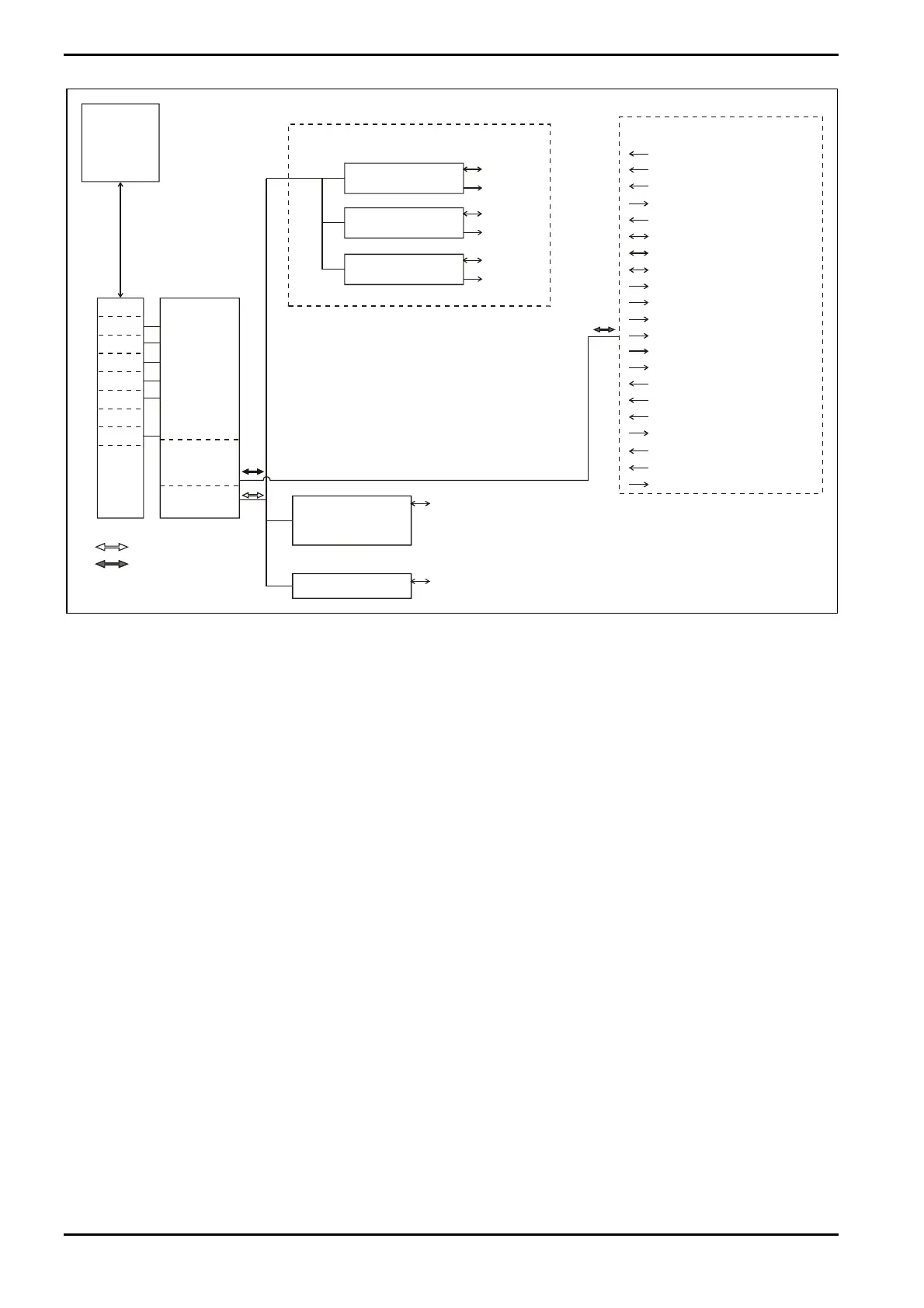
Fig 3-14: Typical control system
The system may be run from the PC terminal in manual mode, that is using direct 'real
time' control over the process, or in automatic mode where the system performs the
entire process according to previously entered recipes. The extensive Oxford Instruments
Plasma Technology process library supports all OpAL configurations. A full description of
the 'PC 2000' control instructions is provided in Section 5.
For details of the control wiring, see the relevant drawings in Volume 2 of this manual.
Description
Issue 1: August 07 Page 3-14 of 46 Printed: 07 August 2009 07:42


 To Next Page