Parker Hannifin
P series User Guide 66
Abnormal response consists of Node ID, Error Code and Exception Code. Packet
structure of abnormal response is the same regardless of the function code.
CRC
Input 16bit CRC value. The values are divided into MSB/LSB, and transmitted one byte
at a time.
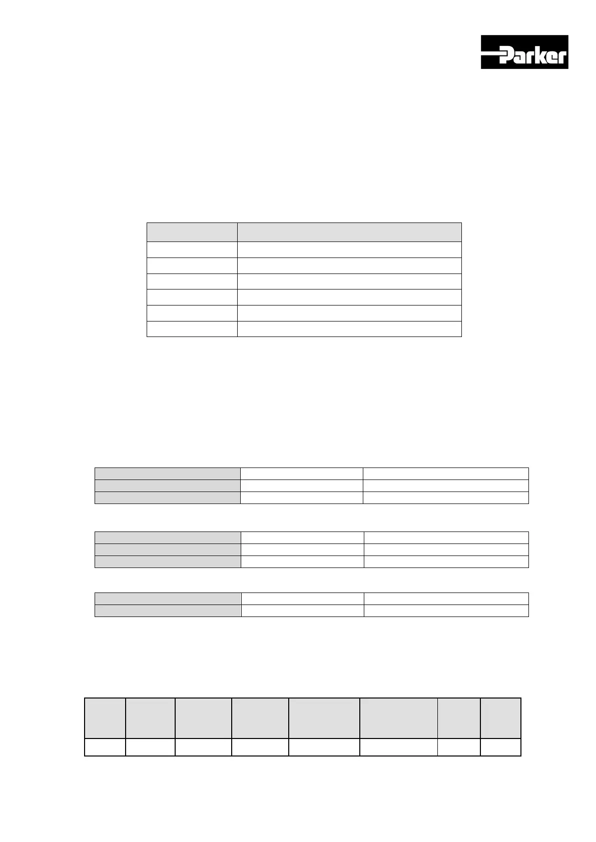
Exception Code
Exception codes for all function code abnormal responses supported by PD Drive are
defined as follows.
Function Code not supported
Table 24. Exception Code Description
4.2.4 Protocol Command Code Description
A. Read Holding Register (0x03)
Reads the values of single register (16bit data) and continuous register block (16bit
data unit).
Request
Request OK
*N = Quantity of Registers
Response not OK
Table 25. Read Holding Register
Example1) reading a single parameter (current speed (Address: 0x2600))
Request
 Loading...


