Parker Hannifin
P series User Guide 83
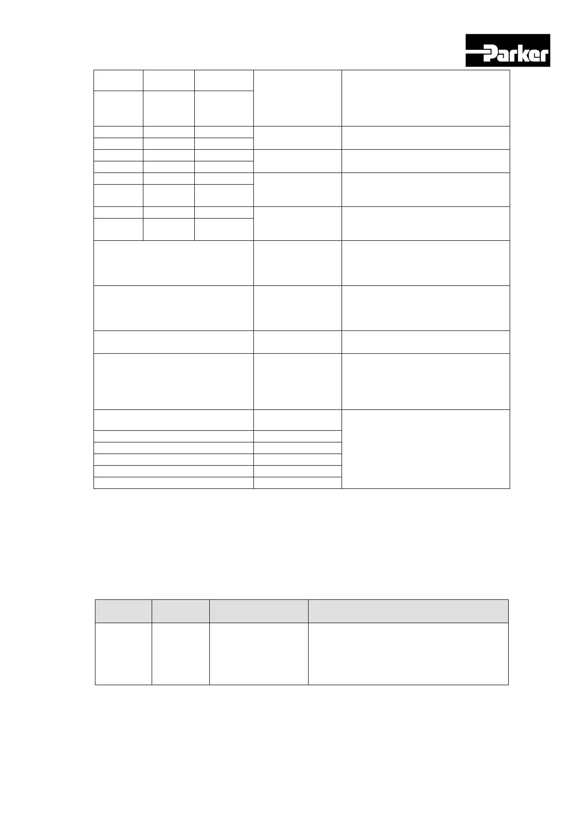
This signal is displayed when the
command position is reached. You
can set the display conditions by
adjusting the [0x2401], [0x2402]
values.
Original position
reached
This signal is displayed when origin
operation is complete.
This signal is displayed when index
operation is complete.
This signal is displayed when the
motor rotates faster than the set
[0x2405] value.
This signal is displayed when the
drive output is limited within the set
torque limit value.
This signal is displayed when the
motor reaches the speed limit. The
speed limit can be adjusted by setting
the [0x230D], [0x230E] values.
This signal is displayed when the
difference between the command
speed and the current speed is under
the set [0x2406]value.
This signal is displayed when a
warning sets off.
This signal is displayed when the
command position is reached. You
can set the display conditions by
adjusting the [0x2401], [0x2402]
values.
This signal displays the number of
the index currently performed (0~63)
Table 48. Digital Output Signal Description
Note ) **These signals are not allotted at the time of the product‘s release from the factory.
You can change allotment by configuring the parameters. Please see “ 4.5 I/O Signal
Setting “ for further details.
4.4.2 Analog I/O
Analog Input Signals (I/O Connector)
-10~+10Vis connected between A-
TLMT(AI1) and AGND to limit the motor‘s
output torque. The relationship between input
voltage and torque limit varies depending on
the set [0x221C] value.
 Loading...


