Parker Hannifin
P series User Guide 105
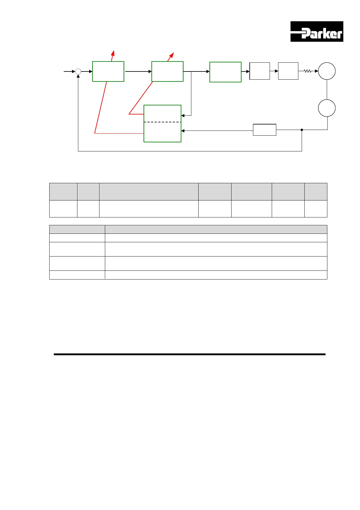
Position Control
Velocity Control
-
+
Inertia
Estimation
Vibration
Frequency
Measurement
Ref.
Position Feedback
Adaptive Filter
Current
Control
Motor
Encoder
Space
Vector
Control
PWM
Control
Velocity
Calculation
Velocity Feedback
Figure 34. Adaptive Filter Diagram
5.7.3 Related Objects
Adaptive Filter Function Select
Uses only 1 adaptive filter. The automatically set values can be confirmed at
notch filter 4 setting (0x250A, 0x250B).
Uses only 2 adaptive filters. The automatically set values can be confirmed at
notch filter3 (0x2507, 0x2508) and notch filter 4 (0x250A, 0x250B) setting.
Table 65. Adaptive Filter Related Objects
The drive provides 2-channel analog monitor output, for drive gain tuning or internal status
parameter monitoring.
 Loading...


