Parker Hannifin
P series User Guide 148
Trigger by Index(Z) pulse
Related Objects
Touch Probe 1 Positive Edge
Position Value
Touch Probe 1 Negative Edge
Position Value
Touch Probe 2 Positive Edge
Position Value
Touch Probe 2Negative Edge
Position Value
Table 83. Touch Probe Function Related Objects
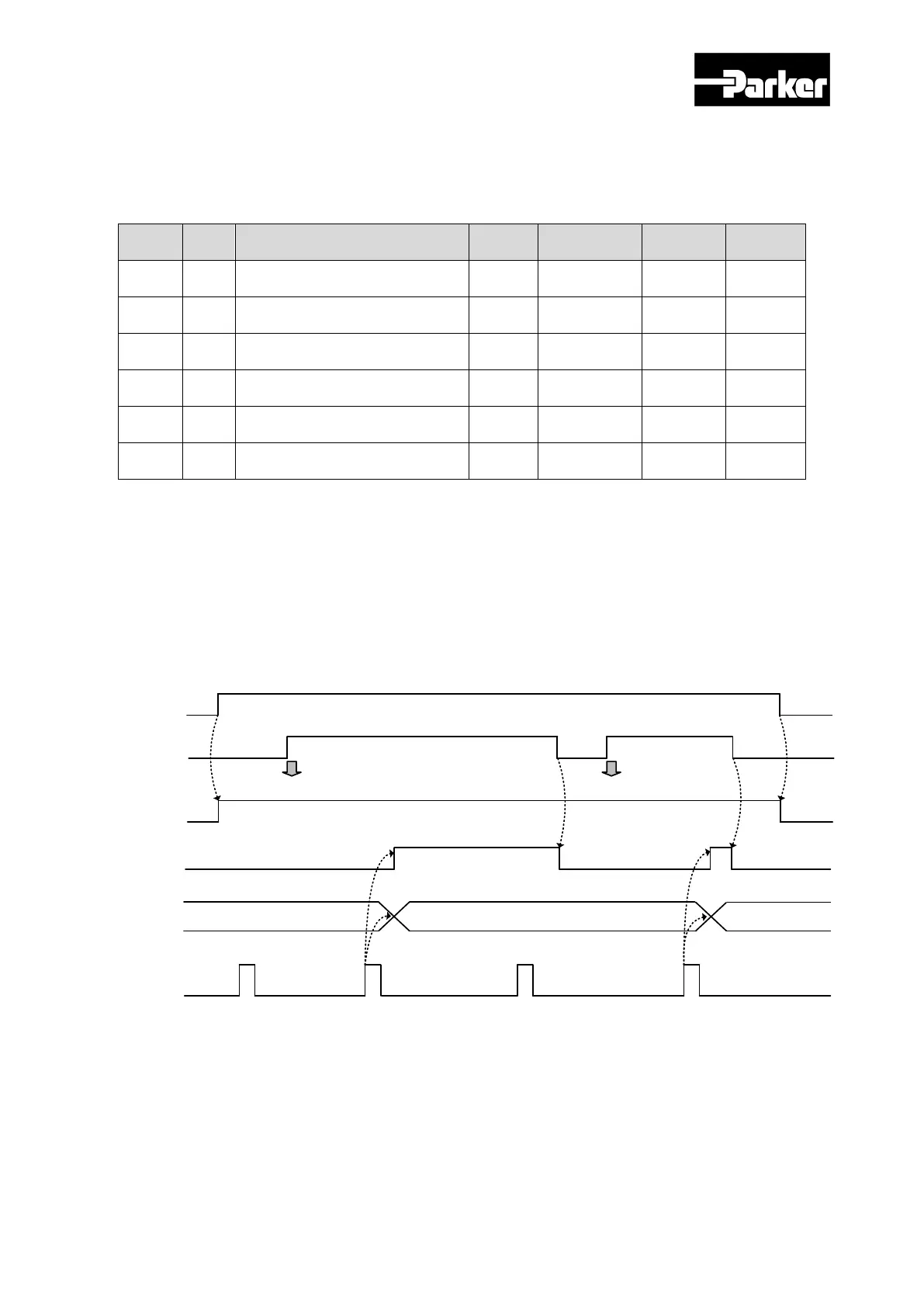
Touch Probe Timing Diagram
Single Trigger Mode (0x60B8.1=0, 0x60B8.9=0):
In command to reset Bit 1, 2,9,10 of the touch probe status (0x60B9) at the single trigger
mode, set the relevant bits (4, 5, 12, 13) of touch probe function (0x60B8) to 0.
0x60B8.0
(0x60B8.8)
0x60B8.4
(0x60B8.12)
0x60B9.0
(0x60B9.8)
Probe input
0x60B9.1
(0x60B9.9)
0x60BA
(0x60BC)
Position 1 Latched
Position 3 Latched
Latch start Latch start
1
2
3
Continuous Trigger Mode (0x60B8.1=1, 0x60B8.9=1):
At continuous trigger mode, Bits 6, 7, 14, 15 of touch probe status (0x60B9) toggles between 0
and 1 every time the relevant input/edge is input.
 Loading...


