EasyManua.ls Logo

Parker PD-04 Series

Parker PD-04 Series
286 pages
To Next Page IconTo Next Page
To Previous Page IconTo Previous Page
Loading...
Parker Hannifin
P series User Guide 115
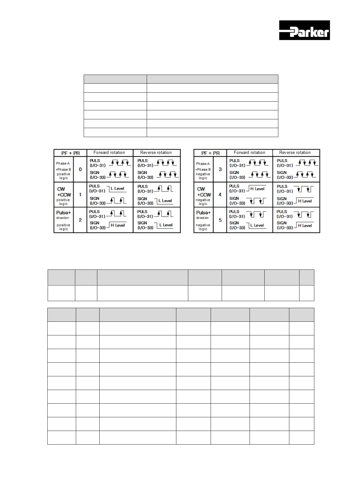
6.1.1 Function Setting of Pulse Input Logic
You can set the logic of the pulse strings from the host controller. The shapes of
the input pulses and the direction of rotation for each logic are as follows.
Set Values
Details
0
PHASE A + PHASE B, Positive Logic
1
CW + CCW, Positive Logic
2
Pulse + Sign, Positive Logic
3
PHASE A+PHASE B, Negative Logic
4
CW + CCW, Negative Logic
5
Pulse + Sign, Negative Logic
6.1.2 Related Objects
Index
Sub
Index
Name
Variable
Format
Accessibility
PDO
Allocation
Unit
0x3003
-
Pulse Input Logic Select
UINT
RW
No
-
Index
Sub
Index
Name
Variable
Format
Accessibility
PDO
Allocation
Unit
0x6041
-
Status word
UINT
RO
Yes
-
0x6062
-
Position Demand Value
DINT
RO
Yes
UU
0x60FC
-
Position Demand Internal
Value
DINT
RO
Yes
pulse
0x6063
-
Position Actual Internal
Value
DINT
RO
Yes
pulse
0x6064
-
Position Actual Value
DINT
RO
Yes
UU
0x60B1
-
Speed Offset
DINT
RW
Yes
UU/s
0x60B2
-
Torque Offset
INT
RW
Yes
0.1%
0x606C
-
Speed Actual Value
DINT
RO
Yes
UU/s
0x6077
-
Torque Actual Value
INT
RO
Yes
0.1%

Table of Contents

Related product manuals