Parker Hannifin
P series User Guide 84
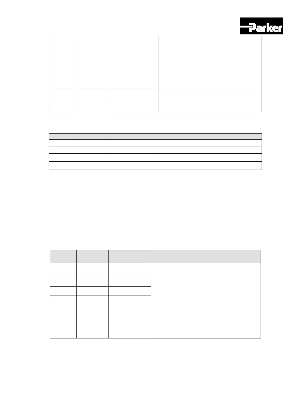
-10~+10Vis connected between A-
OVR(AI2)and AGND to override index
operation speed.
The override value is 0% under -10Vinput,
100% under 0V input, and 200% under
+10V input. You can choose whether to use
this function by [0x221E] or AVOR contact
input.
Table 49. Analog Input Signal Description
Analog Output Signals (Analog Monitoring Connector)
Analog monitor output(-10V ~ +10V)
Analog monitor output(-10V ~ +10V)
Table 50. Analog Output Signal Description
Note) You can change the output variables to monitor through analog monitor output by
adjusting the parameters. Please see “ 5.8 Analog Monitor “ for further details.
4.4.3 Pulse Heat Input
Pulse train Input Signals(I/O Connector)
Inputs command pulse train.
Inputs forward pulse train between PF+ and
PF-, and inputs reverse pulse train between
PR+ and PR-.
The action is performed when the Pulse Input
Position is selected at [0x3000]. Pulse logic
can be configured at [0x3003], and the pulse
input filter can be configured at [0x3004].
When using the line drive method, the
maximum input frequency is 1Mpps. When
using the open collector method, the maximum
input frequency is 200kpps.
Table 51. Pulse Train Input Signal Description
 Loading...


